
User manual


Modules
www.ti.com
• 8-bit immediate instructions embedded in opcode, extendable to 16-bit using a prefix instruction
• Powerful memory-addressing modes
• Efficient manipulation of single bits in I/O space
• Dedicated support for efficient handling of external events
• Vectorized reset and wake-up events allow direct branch to handler address in vector table
• Multiple power-down features, including clock-stop when waiting for external events and wakeup
• Low-power implementation with explicit power gating
• 2-clock execution for all instructions (3 for prefixed instructions)
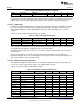
17.4.1.2 Registers
The sensor controller has 8 16-bit general purpose registers, r0 to r7. The registers are used as operands
in all data operations, and also for memory and I/O addressing. All integer registers can be used for any
operation, except for a few instructions that require dedicated use of the integer registers r0 or r1 only.
The size of a register is known as a word, and all operations operate on entire words; there are no such
concepts as byte, half-words, and so forth.
Dedicated flag registers implement the traditional Zero (Z), Negative (N), Carry (C), and Overflow (V)
status indications. A dedicated loop count and loop address register support highly-efficient looping
instructions, and a program counter (PC) for addressing the instruction memory. A built-in 3-level stack
stores the PC during subroutine calls.
Most of the sensor controller registers are memory-mapped and available for the system CPU to read or
write. These are found in the [AUX_SCE:FETCHSTAT] and [AUX_SCE:CPUSTAT] registers.
17.4.1.3 Interfaces
The sensor controller has several interfaces:
• Instruction interface towards AUX RAM
• Data interface towards AUX RAM
• I/O interface towards the peripheral bus
• Event interface towards the event control module
• Power management interface towards the AUX wakeup controller
The data, I/O, and instruction interfaces are all 16-bit interfaces. The data and instruction interfaces are
time-interleaved, so both can access the AUX RAM without affecting each other. The CPU automatically
selects the interface based on the instruction being used.
17.4.1.4 Events, Sleep, and Clock Management
The sensor controller has 8 events connected to its event inputs, that are used with the WEV0 / WEV1
instructions (Wait for event to be 0 or 1). In addition, before executing the SLEEP instruction it is possible
to configure four additional events that will wake up the sensor controller.
These events are used to control program flow upon wakeup as well as saving power.
17.4.1.4.1 WEV1, WEV0 , and SLEEP Instructions
The WEV1, WEV0 , and SLEEP instructions take a parameter which is an event number (event 0 to 7).
When the instruction is executed, the clock stops until the selected event line reaches 0 if it is a WEV0
instruction, or reaches 1 if it is a WEV1 instruction. The events are described in Section 17.4.2.1
The SLEEP instruction also stops the clock but also triggers the AUX power domain to go into a low
power mode if AUX is set up to do so. See Section 17.5, Power Management, for more details.
The sensor controller continues execution from one of its four input wake-up vectors in the
[AUX_EVCTL:VECCFG0] and [AUX_EVCTL:VECCFG1] registers, which are prioritized from 0 (highest) to
3 (lowest).
1192
AUX – Sensor Controller with Digital and Analog Peripherals SWCU117A–February 2015–Revised March 2015
Submit Documentation Feedback
Copyright © 2015, Texas Instruments Incorporated