
User manual


Cortex-M3 Processor Registers
www.ti.com
2.7.3.1 CTRL Register (Offset = 0h) [reset = X]
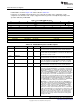
CTRL is shown in Figure 2-61 and described in Table 2-86.
Control This register is used to enable the flash patch block.
Figure 2-61. CTRL Register
31 30 29 28 27 26 25 24
RESERVED
R-X
23 22 21 20 19 18 17 16
RESERVED
R-X
15 14 13 12 11 10 9 8
RESERVED NUM_CODE2 NUM_LIT
R-X R-X R-2h
7 6 5 4 3 2 1 0
NUM_CODE1 RESERVED KEY ENABLE
R-6h R-X W-X R/W-X
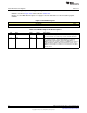
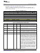
Table 2-86. CTRL Register Field Descriptions
Bit Field Type Reset Description
31-14 RESERVED R X
Software should not rely on the value of a reserved. Writing any
other value than the reset value may result in undefined behavior.
13-12 NUM_CODE2 R X
Number of full banks of code comparators, sixteen comparators per
bank. Where less than sixteen code comparators are provided, the
bank count is zero, and the number present indicated by
NUM_CODE1. This read only field contains 3'b000 to indicate 0
banks for Cortex-M processor.
11-8 NUM_LIT R 2h
Number of literal slots field. 0x0: No literal slots 0x2: Two literal slots
7-4 NUM_CODE1 R 6h
Number of code slots field. 0x0: No code slots 0x2: Two code slots
0x6: Six code slots
3-2 RESERVED R X
Software should not rely on the value of a reserved. Writing any
other value than the reset value may result in undefined behavior.
1 KEY W X
Key field. In order to write to this register, this bit-field must be
written to '1'. This bit always reads 0.
0 ENABLE R/W X
Flash patch unit enable bit 0x0: Flash patch unit disabled 0x1: Flash
patch unit enabled
118
SWCU117A–February 2015–Revised March 2015
Submit Documentation Feedback
Copyright © 2015, Texas Instruments Incorporated