
User's Manual
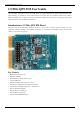
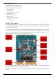
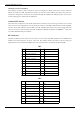
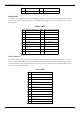

Table Of Contents

CC256x QFN EM User Guide
4
Measuring Current Consumption
These jumpers can also be used to measure the current consumption by placing current sense resistors on R10 for
VBAT_CC and R7 for VDD_1V8. Both these resistors are 0.10 Ohm, 1/4 W. VBAT_CC jumper can be used to to
measure the voltage/power consumed by the CC256x including RF TX/RX while VDD_IO jumper can be used to
measure voltage/power consumed by the digital I/O's.
Antenna/U.FL Selector
The board can be configured to route the RF output from the CC256x to the on board copper antenna or the on board
U.FL connector. This configuration is done by placing the resistor in either R29 or R30 position which has negligible
resistance of a 0 Ohm. R30 will connect the RF to the U.FL while R29 will connect to the copper antenna. The U.FL
connector is used for conducted testing of the RF. The Bluetooth Hardware Evaluation Tool (BHET)
[2]
can be used
to test basic RF functionality on this board.
RF Connectors
The RF1 and RF2 connectors can be used to mount on a wide variety of TI MCU platforms such as MSP430 and
Stellaris. Note that the RF I/O's are all at 3.3V levels. This enables seamless integration of the host using TI's
platforms that comes preinstalled with EM headers. The standard pinout is described in the following table:
RF1
Pin # EM Adapter Pin Assignment Pin # EM Adapter Pin Assignment
1 GND 2 N/C
3 MODULE_UART_CTS 4 N/C
5 SLOW_CLK 6 N/C
7 MODULE_UART_RX 8 N/C
9 MODULE_UART_TX 10 N/C
11 N/C 12 N/C
13 N/C 14 N/C
15 N/C 16 N/C
17 N/C 18 N/C
19 GND 20 N/C
RF2
Pin # EM Adapter Pin Assignment Pin # EM Adapter Pin Assignment
1 N/C 2 GND
3 N/C 4 N/C
5 N/C 6 N/C
7 +3.3V 8 MODULE_AUDIO_DATA_OUT
9 +3.3V 10 MODULE_AUDIO_DATA_IN
11 MODULE_AUDIO_FSYNC 12 N/C
13 N/C 14 N/C
15 N/C 16 N/C