
User manual


swru209
b
7
/
28
5
Getting
started
5.1
Setting up the hardware
After opening the kit, make sure you have all components. Please contact your TI Sales
Representative or TI Support
[17]
if anything is missing.
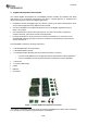
Start by connecting the antennas to the SMA connector on the RF evaluation boards. Tighten the
antenna’s screw firmly on to the SMA connector. If not properly connected, you might see reduced RF
performance. It is also possible to
connect the EM board to RF instruments via coax cables. The EM is
designed to match a 50 Ohm load at the SMA connector.
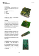
Figure
2
CC2530ZDK assembled hardware
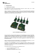
Next, the evaluation modules should be plugged in to the SmartRF0
5EB’s and to the SmartRF05BB’s.
A ZigBee sensor demo application is preprogrammed on the CC2530EM’s included in this kit. The
application consists of two different device types; collectors and sensors. 5 of the CC2530EM’s are
programmed as the sensor devic
e type. When running the out of the box demonstration the sensor
EM’s shall be connected to the BB’s. The two EM’s programmed as collector device shall be
connected to the EB’s.
When not using the out of the box demonstration (i.e. the preprogrammed appl
ication) e.g, for RF
evaluation or software development, all of the 7 EM’s can be used equally.
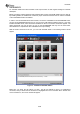
The purpose of the SmartRF05EB is to serve as a general I/O board for testing of the various
peripherals of the CC2530 microcontroller. The SmartRF05EB is also used for programming and
debugging of the CC2530, and has several useful peripheral devices like
LCD, LED’s, I/O connectors,
push buttons and joystick etc.
The evaluation board can be powered from several different sources:
2 x 1.5V AA batteries (included in this kit)
USB (via the USB connector)
DC power (4 to 10 Volt) (not included in this kit)