
User manual


swru209
b
23
/
28
Figure
13
Program/debug with SmartRF05EB
The pin out of this connector is depicted below. For debugging and programming of the SoC the
followi
ng signals are used; SoC RESET_N, DD and DC. In addition GND and +3.3V shall be
connected.
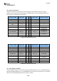
Figure
14
SmartRF05BB SoC Debug Connector
As seen on
Figure
14
also the SPI signals CS, MISO, MOSI and SCLK can be found on this
connector.
10.6
Current Measurement Jumper
Jumper P7, also called V_EM, has been added to the board to simplify current consumption
measurements.
By
removing the jumper, an Ampere Meter can easily be connected to the board to
perform current consumption measurements. Similarly, a separate, regulated power supply for the EM
can be connected. Refer to the schematics (in the appendices) for further detai
ls.