
User manual


swru209
b
21
/
28
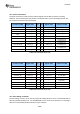
Figure
11
-
Switch P8 effect on LED 1
-
4
Due to lack of pins, some of the signals are shared.
The chip select signal to the EM will also be affected when LED3 is used by the SoC (e.g. CC2530). In
most cases, this will not be a problem, s
ince the SoC does not, by default, implement a SPI slave.
When LED4 is used by the SoC, the signal from Button 1 might interfere. In short, Button 1 and LED 4
can not be used simultaneously by the SoC.
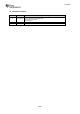
Figure
12
-
Switch P8 effect on Button 1
The EM Selection switch will change the polarity of button number 1.
In the MSP position, the button is active low, i.e. low voltage when the button is pressed. In the
inactive position, the level is high (sig
nal is pulled up by a 10k Ohm resistor).
In the SoC position, the button is active high, i.e. high voltage when the button is pressed. In the
inactive position, the level is low (signal is pulled down by a 10k Ohm resistor).
Note that it is possible to
use this feature to determine the position of switch P8 (assuming the button
is not pressed).