
User manual


swru209
b
20
/
28
Function on BB
Pin
Pin
Function on BB
JOYSTICK_PUSH
1
2
GND
NC
3
4
IO_LED2_MSP
Not in use on BB
5
6
IO_LED3_MSP
VCC_EM
7
8
IO_LED4_MSP
VCC_EM
9
10
NC
JOYSTICK_UP
11
12
Not in use on BB
JOYSTICK_LEFT
13
14
Not in use on BB
SoC Debug P3.7 &
Flash Reset
15
16
IO_BUTTON2
Not in use on BB
17
18
Not in use on BB
JOY_MOVE
19
20
Not in use on BB
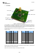
Table
6
EM connector P2 pin out
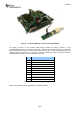
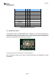
10.3
EM Selection Switch
The EM selection switch on SmartRF05BB controls a multiplexer on the board that allows either a
connected RF SoC EM or
an MSP430 add
-
on board to access all four LEDs on the evaluation board.
The limitation was caused by the particular pin
-
out on the RF evaluation modules that needed to be
backwards compatible with other boards and test equipment.
Figure
10
-
EM Selection Switch (P8)
The switch will both affect the operation of the LEDs and Button 1.
NB: The
EM Selection
switch shall be placed in position SoC/TRX when the CC2530EM is used with
SmartRF05BB.