
User manual


swru209
b
18
/
28
10
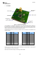
SmartRF05 Battery Board
Figure
9
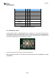
SmartRF05 Battery Board
The SmartRF05 Battery Board is a smaller and simpler board than the
SmartRF05EB. The Battery
Board can together with an EM be used as a standalone node.
Figure
9
shows the SmartRF05 Battery
Board. The Battery Board is powered with 2 AA
batteries placed in the battery connectors underneath
the board.
The peripherals that are available include 2 push buttons, a joystick with 5 directions and 4 LED’s of
different colours that can be controlled via the EM.
There are 2 switches on the SmartRF05 Battery Board:
The
Power
switch P6 used to switch the board’s power supply on/off.
The
EM selection
switch.
NB: The
EM selection switch
shall be placed in position
SoC/TRX
when using a SoC EM such as
CC2530EM or a transceiver EM is connected to the Battery Board.
The position MSP is used when the CCMSP
-
EM430F2618 board (not part of this kit) is connected. More
information about the
EM Selection switch
is found in section
10.3
.
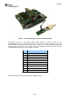
The following sections give the pin out of the different connectors on the SmartRF05 Battery Board.
Refer to the schematics (in the appendic
es) and layout (available on the web) for additional details.
256kB SPI
Flash Module
EM
Connectors
Joystick
EM Selection
Switch
LEDs
Probe
Connectors
Push
Buttons
Power
Switch