
User manual


swru209
b
10
/
28
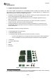
Figure
4
-
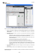
CC2530 control panel in SmartRF Studio
Figure
4
shows the main control panel for the CC2530. It lets you perform a number of oper
ations:
Run TX Test modes for testing of RF output power and spectrum; e.g. by connecting a
spectrum analyser or a power meter to the CC2530EM SMA connector to perform RF
measurements.
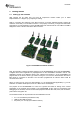
Run Packet TX and RX tests. For this test, you should have two EBs wit
h CC2530EMs
connected to the PC.
o
Double click on both of the devices in the device list in SmartRF Studio (
Figure
3
),
opening two windows, giving control of the two
radios at the same time.
o
Select one device to be the transmitter, by selecting the “Packet TX” tab shown in the
lower middle of
Figure
4
.
o
On the other device (the rec
eiver), select the “Packet RX” tab.
o
Set up basic test parameters and press the “Start
” button for the receiver.
o
Now you can start transmission by pressing the “Start” button for the transmitter.
o
The window
will show the number of packets sent on the transm
itter side and the
number of received packets and signal strength of the last received packet on the
receiver side.
Read and/or modify registers and common settings, such as RF frequency (or channel) and
output power.
Export RF register values in a user mo
difiable format by selecting “File
Register Export
”.
SmartRF Studio
offers a lot of possibilities for testing and evaluating the hardware. Download the tool
and try it for yourself.