
User manual

SWRA274A
June 2010
2/2
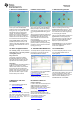
7. Power on collector device
Power up the other SmartRF05EB
(Collector device). Press joystick center
during power up
1
. The green LED 1 will
blink shortly during connecting to the
network. The red LED 2 will blink to
indicate it is in process of discovery and
binding. LED 1 and LED 2 will both be
switched on when the device has joined
the network and bound to the gateway.
Press joystick down to start sending
periodic reports from this device. The
collector node will be displayed as a blue
circle in the ZSensorMonitor as shown in
the image.
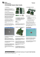
8. Add 2 sensor nodes
Add 2 of the sensor nodes (SmartRF05
Battery boards) to achieve the topology
shown above. Power them up one by one
and press joystick center during power
up
1
.
After the LED’s start blinking rapidly press
joystick down to start the reporting. The
two sensor nodes will appear in the
ZSensorMonitor as soon as their first
report is received.
Press joystick left on the gateway node
(device connected to the PC). The
gateway will then not accept new joining
requests in order to achieve the desired
topology (see step 9).
9. Add remaining sensors
Add the 3 remaining sensors. Press
joystick center during power up
1
. These
sensors will not join the gateway but the
other Collector device since the gateway
is not accepting join requests.
After the LED’s start blinking rapidly press
joystick down to start reporting from
each of the sensors. All of the nodes will
appear in the ZSensorMonitor that will
display the reported temperature.
Congratulations! You have successfully
setup a small ZigBee network and the
sensor demo application.
10. Demo of ZigBee Features
The resulting setup can be used to
demonstrate two of the many benefits
of the ZigBee protocol.
Range extension
The topology in the figure of Step 9
illustrates that ZigBee can be used to
extend the range of a network by using
hops between communicating nodes.
Self-healing
To demonstrate the self-healing feature of
ZigBee you can simply turn off the
collector device that is not connected to
the PC; then the sensors will join the
gateway device (if in radio range) as the
gateway does not allow new devices to
join, but it does allow re-joins of nodes
that are already in the network.
11. IAR Embedded Workbench
To develop software, program and debug
the CC2530, you should use the IAR
Embedded Workbench for 8051.
A free evaluation version of IAR EW8051
is included in the kit. See also
www.iar.com/ew8051.
(See the Z-Stack™ release notes for
details regarding which version to use.)
12. Packet Sniffer
In order to debug RF protocols, one can
use TI’s SmartRF Packet Sniffer to
capture packets.
The packet sniffer software can be found
in the Tools & Software section of the
CC2530 product page [2]. It can be used
with the CC2531 USB dongle or the
SmartRF05EB with a CC2530EM
A. References and more
information
[1] CC2530 ZigBee Development Kit
www.ti.com/cc2530zdk
[2] CC2530 product web page
www.ti.com/cc2530
The Low Power RF Online Community
has forums, blogs and videos. Use the
forums to find information, discuss and
get help with your design. Join us at
www.ti.com/lprf-forum
B. Software references
Z-Stack™ Software
In order to start software development for
ZigBee applications on CC2530, TI’s
ZigBee compliant protocol stack is
required. You can find it on the Z-stack™
product page: www.ti.com/z-stack
Sensor Demo source code
Source code and IAR projects for the
Sensor Demo can be found in the Sensor
Demo software package on the
CC2530ZDK product page:
www.ti.com/cc2530zdk