
User manual

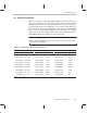
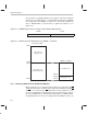

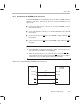
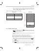
Table Of Contents
- Read This First
- Contents
- Figures
- Tables
- Examples
- Cautions
- Introduction
- Architectural Overview
- Central Processing Unit
- Memory and I/O Spaces
- Program Control
- Addressing Modes
- Assembly Language Instructions
- Instruction Set Summary
- How To Use the Instruction Descriptions
- Instruction Descriptions
- ABS
- ABS
- ADD
- ADD
- ADD
- ADD
- ADDC
- ADDC
- ADDS
- ADDS
- ADDT
- ADDT
- ADRK
- AND
- AND
- AND
- APAC
- APAC
- B
- BACC
- BANZ
- BANZ
- BCND
- BCND
- BIT
- BIT
- BITT
- BITT
- BLDD
- BLDD
- BLDD
- BLDD
- BLDD
- BLPD
- BLPD
- BLPD
- BLPD
- CALA
- CALL
- CC
- CC
- CLRC
- CLRC
- CMPL
- CMPR
- DMOV
- DMOV
- IDLE
- IN
- IN
- INTR
- LACC
- LACC
- LACC
- LACL
- LACL
- LACL
- LACT
- LACT
- LAR
- LAR
- LAR
- LDP
- LDP
- LPH
- LPH
- LST
- LST
- LST
- LST
- LT
- LT
- LTA
- LTA
- LTD
- LTD
- LTD
- LTP
- LTP
- LTS
- LTS
- MAC
- MAC
- MAC
- MAC
- MACD
- MACD
- MACD
- MACD
- MACD
- MAR
- MAR
- MPY
- MPY
- MPY
- MPYA
- MPYA
- MPYS
- MPYS
- MPYU
- MPYU
- NEG
- NEG
- NMI
- NOP
- NORM
- NORM
- NORM
- OR
- OR
- OR
- OUT
- OUT
- PAC
- POP
- POP
- POPD
- POPD
- PSHD
- PSHD
- PUSH
- RET
- RETC
- ROL
- ROR
- RPT
- RPT
- SACH
- SACH
- SACL
- SACL
- SAR
- SAR
- SBRK
- SETC
- SETC
- SFL
- SFR
- SFR
- SPAC
- SPH
- SPH
- SPL
- SPL
- SPLK
- SPLK
- SPM
- SQRA
- SQRA
- SQRS
- SQRS
- SST
- SST
- SUB
- SUB
- SUB
- SUB
- SUBB
- SUBB
- SUBC
- SUBC
- SUBS
- SUBS
- SUBT
- SUBT
- TBLR
- TBLR
- TBLR
- TBLW
- TBLW
- TBLW
- TRAP
- XOR
- XOR
- XOR
- ZALR
- ZALR
- On-Chip Peripherals
- Synchronous Serial Port
- Asynchronous Serial Port
- TMS320C209
- Register Summary
- TMS320C1x/C2x/C2xx/C5x Instruction Set Comparison
- Program Examples
- Submitting ROM Codes to TI
- Design Considerations for Using XDS510 Emulator
- E.1 Designing Your Target System’s Emulator Connector (14-Pin Header)
- E.2 Bus Protocol
- E.3 Emulator Cable Pod
- E.4 Emulator Cable Pod Signal Timing
- E.5 Emulation Timing Calculations
- E.6 Connections Between the Emulator and the Target System
- E.7 Physical Dimensions for the 14-Pin Emulator Connector
- E.8 Emulation Design Considerations
- Glossary
- Index

Boot Loader
4-16
4.5.3 Programming the EPROM
Texas Instruments fixed-point development tools provide the utilities to gener-
ate the boot ROM code. (For an introduction to the procedure for generating
boot loader code, see Appendix C,
Program Examples
.) However, should you
need to do the programming, use the following procedure.
Store the following to the EPROM:
Destination address. Store the destination address in the first two bytes
of the EPROM—store the high-order byte of the destination address at
EPROM address 8000h and store the low-order byte at EPROM address
8001h.
Program length. Store N (the length of your program in bytes) in the next
two bytes in EPROM. Use this calculation to determine N:
N = ((number of bytes to be transferred)/2) – 1
Store the high-order N byte at EPROM address 8002h and the low-order N
byte at EPROM address 8003h.
Program. Store the program, one byte at a time, beginning at EPROM ad-
dress 8004h.
Each word in the program must be divided into two bytes in the EPROM;
store the high-order byte first and store the low-order byte second. For ex-
ample, if the first word were 813Fh, you would store 81h into the first byte
(at 8004h) and 3Fh into the second byte (at 8005h). Then, you would store
the high byte of the next word at address 8006h.
Notes:
1) Do not include the first four bytes of the EPROM in your calculation of
the length (N). The boot loader uses N beginning at the fifth byte of the
EPROM.
2) Make sure the first part of the program on the EPROM contains code for
the reset and interrupt vectors. These vectors must be stored in the des-
tination RAM first, so that they can be fetched from program-memory ad-
dresses 0000h–003Fh. The reset vector will be fetched from 0000h. For
a list of all the assigned vector locations, see subsection 5.6.2,
Interrupt
Table
, on page 5-16.