
User manual
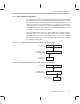
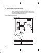
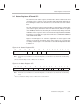
Table Of Contents
- Read This First
- Contents
- Figures
- Tables
- Examples
- Cautions
- Introduction
- Architectural Overview
- Central Processing Unit
- Memory and I/O Spaces
- Program Control
- Addressing Modes
- Assembly Language Instructions
- Instruction Set Summary
- How To Use the Instruction Descriptions
- Instruction Descriptions
- ABS
- ABS
- ADD
- ADD
- ADD
- ADD
- ADDC
- ADDC
- ADDS
- ADDS
- ADDT
- ADDT
- ADRK
- AND
- AND
- AND
- APAC
- APAC
- B
- BACC
- BANZ
- BANZ
- BCND
- BCND
- BIT
- BIT
- BITT
- BITT
- BLDD
- BLDD
- BLDD
- BLDD
- BLDD
- BLPD
- BLPD
- BLPD
- BLPD
- CALA
- CALL
- CC
- CC
- CLRC
- CLRC
- CMPL
- CMPR
- DMOV
- DMOV
- IDLE
- IN
- IN
- INTR
- LACC
- LACC
- LACC
- LACL
- LACL
- LACL
- LACT
- LACT
- LAR
- LAR
- LAR
- LDP
- LDP
- LPH
- LPH
- LST
- LST
- LST
- LST
- LT
- LT
- LTA
- LTA
- LTD
- LTD
- LTD
- LTP
- LTP
- LTS
- LTS
- MAC
- MAC
- MAC
- MAC
- MACD
- MACD
- MACD
- MACD
- MACD
- MAR
- MAR
- MPY
- MPY
- MPY
- MPYA
- MPYA
- MPYS
- MPYS
- MPYU
- MPYU
- NEG
- NEG
- NMI
- NOP
- NORM
- NORM
- NORM
- OR
- OR
- OR
- OUT
- OUT
- PAC
- POP
- POP
- POPD
- POPD
- PSHD
- PSHD
- PUSH
- RET
- RETC
- ROL
- ROR
- RPT
- RPT
- SACH
- SACH
- SACL
- SACL
- SAR
- SAR
- SBRK
- SETC
- SETC
- SFL
- SFR
- SFR
- SPAC
- SPH
- SPH
- SPL
- SPL
- SPLK
- SPLK
- SPM
- SQRA
- SQRA
- SQRS
- SQRS
- SST
- SST
- SUB
- SUB
- SUB
- SUB
- SUBB
- SUBB
- SUBC
- SUBC
- SUBS
- SUBS
- SUBT
- SUBT
- TBLR
- TBLR
- TBLR
- TBLW
- TBLW
- TBLW
- TRAP
- XOR
- XOR
- XOR
- ZALR
- ZALR
- On-Chip Peripherals
- Synchronous Serial Port
- Asynchronous Serial Port
- TMS320C209
- Register Summary
- TMS320C1x/C2x/C2xx/C5x Instruction Set Comparison
- Program Examples
- Submitting ROM Codes to TI
- Design Considerations for Using XDS510 Emulator
- E.1 Designing Your Target System’s Emulator Connector (14-Pin Header)
- E.2 Bus Protocol
- E.3 Emulator Cable Pod
- E.4 Emulator Cable Pod Signal Timing
- E.5 Emulation Timing Calculations
- E.6 Connections Between the Emulator and the Target System
- E.7 Physical Dimensions for the 14-Pin Emulator Connector
- E.8 Emulation Design Considerations
- Glossary
- Index

Central Arithmetic Logic Section
3-10
Status bits. Four status bits are associated with the accumulator:
Carry bit (C).
C (bit 9 of status register ST1) is affected during:
Additions to and subtractions from the accumulator:
C = 0 When the result of a subtraction generates a borrow.
When the result of an addition does not generate a carry. (Ex-
ception: When the ADD instruction is used with a shift of 16 and
no carry is generated, the ADD instruction has no affect on C.)
C = 1 When the result of an addition generates a carry.
When the result of a subtraction does not generate a borrow.
(Exception: When the SUB instruction is used with a shift of 16
and no borrow is generated, the SUB instruction has no effect
on C.)
Single-bit shifts and rotations of the accumulator value. During a left
shift or rotation, the most significant bit of the accumulator is passed to
C; during a right shift or rotation, the least significant bit is passed to C.
Overflow mode bit (OVM).
OVM (bit 11 of status register ST0) determines
how the accumulator will reflect arithmetic overflows. When the processor
is in overflow mode (OVM = 1) and an overflow occurs, the accumulator
is filled with one of two specific values:
If the overflow is in the positive direction, the accumulator is filled with
its most positive value (7FFF FFFFh).
If the overflow is in the negative direction, the accumulator is filled with
its most negative value (8000 0000h).
Overflow flag bit (OV).
OV is bit 12 of status register ST0. When no accu-
mulator overflow is detected, OV is latched at 0. When overflow (positive
or negative) occurs, OV is set to 1 and latched.
Test/control flag bit (TC).
TC (bit 11 of status register ST1) is set to 0 or 1
depending on the value of a tested bit. In the case of the NORM instruction,
if the exclusive-OR of the two MSBs of the accumulator is true, TC is set
to 1.
A number of branch instructions are implemented based on the status of bits
C, OV, and TC, and on the value in the accumulator (as compared to zero). For
more information about these instructions, see Section 5.4,
Conditional
Branches, Calls, and Returns
, on page 5-10.