
User manual
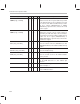
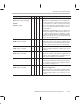

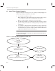
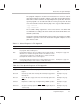
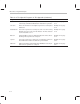

Table Of Contents
- Read This First
- Contents
- Figures
- Tables
- Examples
- Cautions
- Introduction
- Architectural Overview
- Central Processing Unit
- Memory and I/O Spaces
- Program Control
- Addressing Modes
- Assembly Language Instructions
- Instruction Set Summary
- How To Use the Instruction Descriptions
- Instruction Descriptions
- ABS
- ABS
- ADD
- ADD
- ADD
- ADD
- ADDC
- ADDC
- ADDS
- ADDS
- ADDT
- ADDT
- ADRK
- AND
- AND
- AND
- APAC
- APAC
- B
- BACC
- BANZ
- BANZ
- BCND
- BCND
- BIT
- BIT
- BITT
- BITT
- BLDD
- BLDD
- BLDD
- BLDD
- BLDD
- BLPD
- BLPD
- BLPD
- BLPD
- CALA
- CALL
- CC
- CC
- CLRC
- CLRC
- CMPL
- CMPR
- DMOV
- DMOV
- IDLE
- IN
- IN
- INTR
- LACC
- LACC
- LACC
- LACL
- LACL
- LACL
- LACT
- LACT
- LAR
- LAR
- LAR
- LDP
- LDP
- LPH
- LPH
- LST
- LST
- LST
- LST
- LT
- LT
- LTA
- LTA
- LTD
- LTD
- LTD
- LTP
- LTP
- LTS
- LTS
- MAC
- MAC
- MAC
- MAC
- MACD
- MACD
- MACD
- MACD
- MACD
- MAR
- MAR
- MPY
- MPY
- MPY
- MPYA
- MPYA
- MPYS
- MPYS
- MPYU
- MPYU
- NEG
- NEG
- NMI
- NOP
- NORM
- NORM
- NORM
- OR
- OR
- OR
- OUT
- OUT
- PAC
- POP
- POP
- POPD
- POPD
- PSHD
- PSHD
- PUSH
- RET
- RETC
- ROL
- ROR
- RPT
- RPT
- SACH
- SACH
- SACL
- SACL
- SAR
- SAR
- SBRK
- SETC
- SETC
- SFL
- SFR
- SFR
- SPAC
- SPH
- SPH
- SPL
- SPL
- SPLK
- SPLK
- SPM
- SQRA
- SQRA
- SQRS
- SQRS
- SST
- SST
- SUB
- SUB
- SUB
- SUB
- SUBB
- SUBB
- SUBC
- SUBC
- SUBS
- SUBS
- SUBT
- SUBT
- TBLR
- TBLR
- TBLR
- TBLW
- TBLW
- TBLW
- TRAP
- XOR
- XOR
- XOR
- ZALR
- ZALR
- On-Chip Peripherals
- Synchronous Serial Port
- Asynchronous Serial Port
- TMS320C209
- Register Summary
- TMS320C1x/C2x/C2xx/C5x Instruction Set Comparison
- Program Examples
- Submitting ROM Codes to TI
- Design Considerations for Using XDS510 Emulator
- E.1 Designing Your Target System’s Emulator Connector (14-Pin Header)
- E.2 Bus Protocol
- E.3 Emulator Cable Pod
- E.4 Emulator Cable Pod Signal Timing
- E.5 Emulation Timing Calculations
- E.6 Connections Between the Emulator and the Target System
- E.7 Physical Dimensions for the 14-Pin Emulator Connector
- E.8 Emulation Design Considerations
- Glossary
- Index

About These Program Examples
C-3
Program Examples
The program examples in Section C.2 and Section C.3 consist of code for
shared files and task-specific files. Table C–1 describes the shared programs.
Shared files contain code that is used by multiple task-specific files. The task-
specific programs are described in Table C–2. Every task-specific file that
uses the header files includes them by way of the
.copy
assembler directive:
.copy ”init.h”
.copy ”vector.h”
The assembler brings together the .h files and .asm file. The linker links
assembled files according to the device architecture defined in the linker com-
mand file (c203.cmd).
Section C.4 contains an introduction to the procedure for using the assembler
and linker to generate code for the boot loader. Program examples are also
given in that section.
Table C–1. Shared Programs in This Appendix
Program Functional Description See ...
c203.cmd Command file that defines size and placement of address blocks for
the program, data, and I/O spaces
Example C–1, page C-5
init.h Header file that declares space for variables and constants; declares
initial values for variables; designates labels for the addresses of the
control registers mapped to on-chip I/O space; contains comments
that explain the functions of the control registers
Example C–2, page C-6
vector.h Header file that fills the interrupt vector locations with branches to the
corresponding interrupt service routines or with other values
Example C–3, page C-7
Table C–2. Task-Specific Programs in This Appendix
Program Functional Description See ...
delay.asm Creates simple nested delay loops, measurable through XF and
I/O pins
Example C–4, page
C-8
timer.asm Generates periodic timer interrupt, XF and I/O pins toggle at the
interrupt rate
Example C–5, page
C-9
intr1.asm Causes XF pin to toggle at the rate of the interrupt signal on the
INT1
pin
Example C–6, page
C-10
hold.asm Explains the software logic for implementing a HOLD operation Example C–7 page
C-11
intr23.asm
Accepts an interrupt signal on INT2 or INT3. Toggles XF pin for
each interrupt.
Example C–8, page
C-12