
User manual
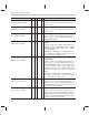
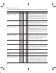
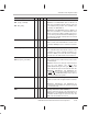
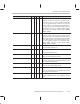
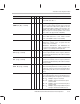
Table Of Contents
- Read This First
- Contents
- Figures
- Tables
- Examples
- Cautions
- Introduction
- Architectural Overview
- Central Processing Unit
- Memory and I/O Spaces
- Program Control
- Addressing Modes
- Assembly Language Instructions
- Instruction Set Summary
- How To Use the Instruction Descriptions
- Instruction Descriptions
- ABS
- ABS
- ADD
- ADD
- ADD
- ADD
- ADDC
- ADDC
- ADDS
- ADDS
- ADDT
- ADDT
- ADRK
- AND
- AND
- AND
- APAC
- APAC
- B
- BACC
- BANZ
- BANZ
- BCND
- BCND
- BIT
- BIT
- BITT
- BITT
- BLDD
- BLDD
- BLDD
- BLDD
- BLDD
- BLPD
- BLPD
- BLPD
- BLPD
- CALA
- CALL
- CC
- CC
- CLRC
- CLRC
- CMPL
- CMPR
- DMOV
- DMOV
- IDLE
- IN
- IN
- INTR
- LACC
- LACC
- LACC
- LACL
- LACL
- LACL
- LACT
- LACT
- LAR
- LAR
- LAR
- LDP
- LDP
- LPH
- LPH
- LST
- LST
- LST
- LST
- LT
- LT
- LTA
- LTA
- LTD
- LTD
- LTD
- LTP
- LTP
- LTS
- LTS
- MAC
- MAC
- MAC
- MAC
- MACD
- MACD
- MACD
- MACD
- MACD
- MAR
- MAR
- MPY
- MPY
- MPY
- MPYA
- MPYA
- MPYS
- MPYS
- MPYU
- MPYU
- NEG
- NEG
- NMI
- NOP
- NORM
- NORM
- NORM
- OR
- OR
- OR
- OUT
- OUT
- PAC
- POP
- POP
- POPD
- POPD
- PSHD
- PSHD
- PUSH
- RET
- RETC
- ROL
- ROR
- RPT
- RPT
- SACH
- SACH
- SACL
- SACL
- SAR
- SAR
- SBRK
- SETC
- SETC
- SFL
- SFR
- SFR
- SPAC
- SPH
- SPH
- SPL
- SPL
- SPLK
- SPLK
- SPM
- SQRA
- SQRA
- SQRS
- SQRS
- SST
- SST
- SUB
- SUB
- SUB
- SUB
- SUBB
- SUBB
- SUBC
- SUBC
- SUBS
- SUBS
- SUBT
- SUBT
- TBLR
- TBLR
- TBLR
- TBLW
- TBLW
- TBLW
- TRAP
- XOR
- XOR
- XOR
- ZALR
- ZALR
- On-Chip Peripherals
- Synchronous Serial Port
- Asynchronous Serial Port
- TMS320C209
- Register Summary
- TMS320C1x/C2x/C2xx/C5x Instruction Set Comparison
- Program Examples
- Submitting ROM Codes to TI
- Design Considerations for Using XDS510 Emulator
- E.1 Designing Your Target System’s Emulator Connector (14-Pin Header)
- E.2 Bus Protocol
- E.3 Emulator Cable Pod
- E.4 Emulator Cable Pod Signal Timing
- E.5 Emulation Timing Calculations
- E.6 Connections Between the Emulator and the Target System
- E.7 Physical Dimensions for the 14-Pin Emulator Connector
- E.8 Emulation Design Considerations
- Glossary
- Index

Instruction Set Comparison Table
B-30
Syntax
Description5x2xx2x1x
SBBB
√
Subtract ACCB From Accumulator With Borrow
Subtract the contents of the ACCB and the logical in-
version of the carry bit from the accumulator. The result
is stored in the accumulator; the accumulator buffer is
not affected. Clear the carry bit if the result generates
a borrow.
SBLK #
lk
[
, shift
]
√ √ √
Subtract From Accumulator Long Immediate
With Shift
Subtract the immediate value from the accumulator. If
a shift is specified, left shift the value before subtract-
ing. During shifting, low-order bits are zero filled, and
high-order bits are sign extended if SXM = 1.
SBRK #
k
√ √ √
Subtract From Auxiliary Register Short
Immediate
Subtract the 8-bit immediate value from the
designated auxiliary register.
SC
√ √ √
Set Carry Bit
Set the C status bit to 1.
SETC
control bit
√ √
Set Control Bit
Set the specified control bit to a logic 1. Maskable
interrupts are disabled immediately after the SETC
instruction executes.
SFL
√ √ √
Shift Accumulator Left
Shift the contents of the accumulator left one bit.
SFLB
√
Shift ACCB and Accumulator Left
Shift the concatenation of the accumulator and the
ACCB left one bit. The LSB of the ACCB is cleared to
0, and the MSB of the ACCB is shifted into the carry bit.
SFR
√ √ √
Shift Accumulator Right
Shift the contents of the accumulator right one bit. If
SXM = 1, SFR produces an arithmetic right shift. If
SXM = 0, SFR produces a logic right shift.
SFRB
√
Shift ACCB and Accumulator Right
Shift the concatenation of the accumulator and the
ACCB right 1 bit. The LSB of the ACCB is shifted into
the carry bit. If SXM = 1, SFRB produces an arithmetic
right shift. If SXM = 0, SFRB produces a logic right shift.
SFSM
√
Set Serial Port Frame Synchronization Mode
Set the FSM status bit to 1.