
User manual
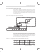
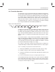
Table Of Contents
- Read This First
- Contents
- Figures
- Tables
- Examples
- Cautions
- Introduction
- Architectural Overview
- Central Processing Unit
- Memory and I/O Spaces
- Program Control
- Addressing Modes
- Assembly Language Instructions
- Instruction Set Summary
- How To Use the Instruction Descriptions
- Instruction Descriptions
- ABS
- ABS
- ADD
- ADD
- ADD
- ADD
- ADDC
- ADDC
- ADDS
- ADDS
- ADDT
- ADDT
- ADRK
- AND
- AND
- AND
- APAC
- APAC
- B
- BACC
- BANZ
- BANZ
- BCND
- BCND
- BIT
- BIT
- BITT
- BITT
- BLDD
- BLDD
- BLDD
- BLDD
- BLDD
- BLPD
- BLPD
- BLPD
- BLPD
- CALA
- CALL
- CC
- CC
- CLRC
- CLRC
- CMPL
- CMPR
- DMOV
- DMOV
- IDLE
- IN
- IN
- INTR
- LACC
- LACC
- LACC
- LACL
- LACL
- LACL
- LACT
- LACT
- LAR
- LAR
- LAR
- LDP
- LDP
- LPH
- LPH
- LST
- LST
- LST
- LST
- LT
- LT
- LTA
- LTA
- LTD
- LTD
- LTD
- LTP
- LTP
- LTS
- LTS
- MAC
- MAC
- MAC
- MAC
- MACD
- MACD
- MACD
- MACD
- MACD
- MAR
- MAR
- MPY
- MPY
- MPY
- MPYA
- MPYA
- MPYS
- MPYS
- MPYU
- MPYU
- NEG
- NEG
- NMI
- NOP
- NORM
- NORM
- NORM
- OR
- OR
- OR
- OUT
- OUT
- PAC
- POP
- POP
- POPD
- POPD
- PSHD
- PSHD
- PUSH
- RET
- RETC
- ROL
- ROR
- RPT
- RPT
- SACH
- SACH
- SACL
- SACL
- SAR
- SAR
- SBRK
- SETC
- SETC
- SFL
- SFR
- SFR
- SPAC
- SPH
- SPH
- SPL
- SPL
- SPLK
- SPLK
- SPM
- SQRA
- SQRA
- SQRS
- SQRS
- SST
- SST
- SUB
- SUB
- SUB
- SUB
- SUBB
- SUBB
- SUBC
- SUBC
- SUBS
- SUBS
- SUBT
- SUBT
- TBLR
- TBLR
- TBLR
- TBLW
- TBLW
- TBLW
- TRAP
- XOR
- XOR
- XOR
- ZALR
- ZALR
- On-Chip Peripherals
- Synchronous Serial Port
- Asynchronous Serial Port
- TMS320C209
- Register Summary
- TMS320C1x/C2x/C2xx/C5x Instruction Set Comparison
- Program Examples
- Submitting ROM Codes to TI
- Design Considerations for Using XDS510 Emulator
- E.1 Designing Your Target System’s Emulator Connector (14-Pin Header)
- E.2 Bus Protocol
- E.3 Emulator Cable Pod
- E.4 Emulator Cable Pod Signal Timing
- E.5 Emulation Timing Calculations
- E.6 Connections Between the Emulator and the Target System
- E.7 Physical Dimensions for the 14-Pin Emulator Connector
- E.8 Emulation Design Considerations
- Glossary
- Index
Transmitter Operation
10-19
Asynchronous Serial Port
10.4 Transmitter Operation
The transmitter consists of an 8-bit transmit register (ADTR) and an 8-bit trans-
mit shift register (AXSR). Data to be transmitted is written to the ADTR, and
then the port transfers the data to the AXSR. Data written to the transmit regis-
ter should be written in right-justified form, with the LSB as the rightmost bit.
Data from the AXSR is shifted out on the TX pin in the serial form shown in
Figure 10–6 (the number of stop bits depends on the value of the STB bit in
the ASPCR). When the serial port is not transmitting, TX should be held high
by clearing the SETBRK bit of the ASPCR (SETBRK = 0).
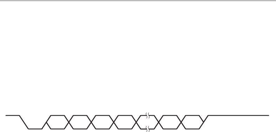
Figure 10–6. Data Transmit
Start Bit 0 Bit 1 Bit 2 Bit 3 Bit 6 Bit 7 Stop 1 Stop 2
Transmission is started by a write to the ADTR. If the AXSR is empty, data from
the ADTR is transferred to the AXSR. If the AXSR is full, then data is kept in
the ADTR, and existing data in the AXSR is shifted out to the sequence control
logic. If both the AXSR and ADTR are full and the CPU tries to write to the
ADTR, the write is not allowed, and existing data in both registers is main-
tained.
If the transmit register is empty and interrupt TXRXINT is unmasked (in the
IMR) and enabled (by the INTM bit), an interrupt is generated. When the ADTR
empties, the THRE bit of the IOSR is set to 1. The bit is cleared when a charac-
ter is loaded into the transmit register. Bit 12 (TEMT) of the IOSR is set if both
the transmit and transmit shift registers are empty.
The sequence control logic constructs the transmit frame by sending out a
start bit followed by the data bits from the AXSR and either one or two stop bits.
Here is a summary of asynchronous mode transmission:
1) An interrupt (TXRXINT) is generated if the transmit register is empty.
2) If AXSR is empty, the data is transferred from ADTR to AXSR.
3) A start bit is transmitted to TX, followed by eight data bits (LSB first), and
the stop bit(s).
4) For the next transmission, the process begins again from step 1.
To avoid double interrupts, the interrupt service routine should clear TXRXINT
in the interrupt flag register (IFR), just before forcing a return from the routine.
Take special care when using this interrupt; it will be generated frequently for
as long as the transmit register is empty.