
User manual
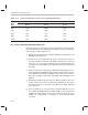
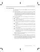
Table Of Contents
- Read This First
- Contents
- Figures
- Tables
- Examples
- Cautions
- Introduction
- Architectural Overview
- Central Processing Unit
- Memory and I/O Spaces
- Program Control
- Addressing Modes
- Assembly Language Instructions
- Instruction Set Summary
- How To Use the Instruction Descriptions
- Instruction Descriptions
- ABS
- ABS
- ADD
- ADD
- ADD
- ADD
- ADDC
- ADDC
- ADDS
- ADDS
- ADDT
- ADDT
- ADRK
- AND
- AND
- AND
- APAC
- APAC
- B
- BACC
- BANZ
- BANZ
- BCND
- BCND
- BIT
- BIT
- BITT
- BITT
- BLDD
- BLDD
- BLDD
- BLDD
- BLDD
- BLPD
- BLPD
- BLPD
- BLPD
- CALA
- CALL
- CC
- CC
- CLRC
- CLRC
- CMPL
- CMPR
- DMOV
- DMOV
- IDLE
- IN
- IN
- INTR
- LACC
- LACC
- LACC
- LACL
- LACL
- LACL
- LACT
- LACT
- LAR
- LAR
- LAR
- LDP
- LDP
- LPH
- LPH
- LST
- LST
- LST
- LST
- LT
- LT
- LTA
- LTA
- LTD
- LTD
- LTD
- LTP
- LTP
- LTS
- LTS
- MAC
- MAC
- MAC
- MAC
- MACD
- MACD
- MACD
- MACD
- MACD
- MAR
- MAR
- MPY
- MPY
- MPY
- MPYA
- MPYA
- MPYS
- MPYS
- MPYU
- MPYU
- NEG
- NEG
- NMI
- NOP
- NORM
- NORM
- NORM
- OR
- OR
- OR
- OUT
- OUT
- PAC
- POP
- POP
- POPD
- POPD
- PSHD
- PSHD
- PUSH
- RET
- RETC
- ROL
- ROR
- RPT
- RPT
- SACH
- SACH
- SACL
- SACL
- SAR
- SAR
- SBRK
- SETC
- SETC
- SFL
- SFR
- SFR
- SPAC
- SPH
- SPH
- SPL
- SPL
- SPLK
- SPLK
- SPM
- SQRA
- SQRA
- SQRS
- SQRS
- SST
- SST
- SUB
- SUB
- SUB
- SUB
- SUBB
- SUBB
- SUBC
- SUBC
- SUBS
- SUBS
- SUBT
- SUBT
- TBLR
- TBLR
- TBLR
- TBLW
- TBLW
- TBLW
- TRAP
- XOR
- XOR
- XOR
- ZALR
- ZALR
- On-Chip Peripherals
- Synchronous Serial Port
- Asynchronous Serial Port
- TMS320C209
- Register Summary
- TMS320C1x/C2x/C2xx/C5x Instruction Set Comparison
- Program Examples
- Submitting ROM Codes to TI
- Design Considerations for Using XDS510 Emulator
- E.1 Designing Your Target System’s Emulator Connector (14-Pin Header)
- E.2 Bus Protocol
- E.3 Emulator Cable Pod
- E.4 Emulator Cable Pod Signal Timing
- E.5 Emulation Timing Calculations
- E.6 Connections Between the Emulator and the Target System
- E.7 Physical Dimensions for the 14-Pin Emulator Connector
- E.8 Emulation Design Considerations
- Glossary
- Index

Controlling and Resetting the Port
10-13
Asynchronous Serial Port
Bit 3 IO3 — Status bit for IO3. When the IO3 pin is configured as an input (by the
CIO3 bit of the ASPCR), this bit reflects the current level on the IO3 pin.
IO3 = 0 The IO3 signal is low.
IO3 = 1 The IO3 signal is high.
Bit 2 IO2 — Status bit for IO2. When the IO2 pin is configured as an input (by the
CIO2 bit of the ASPCR), this bit reflects the current level on the IO2 pin.
IO2 = 0 The IO2 signal is low.
IO2 = 1 The IO2 signal is high.
Bit 1 IO1 — Status bit for IO1. When the IO1 pin is configured as an input (by the
CIO1 bit of the ASPCR), this bit reflects the current level on the IO1 pin.
IO1 = 0 The IO1 signal is low.
IO1 = 1 The IO1 signal is high.
Bit 0 IO0 — Status bit for IO0. When the IO0 pin is configured as an input (by the
CIO0 bit of the ASPCR), this bit reflects the current level on the IO0 pin.
IO0 = 0 The IO0 signal is low.
IO0 = 1 The IO0 signal is high.
10.3.3 Baud-Rate Divisor Register (BRD)
The baud rate of the asynchronous serial port can be set to many different
rates by means of the BRD, an on-chip register located at address FFF7h in
I/O space. Equation 10–1 shows how to set the BRD value to get the desired
baud rate. When the BRD contains 0, the ASP will not transmit or receive any
character. At reset, BRD = 0001h.
Equation 10–1. Value Needed in the BRD
BRD value in decimal = CLKOUT1 frequency
16 × desired baud rate
Table 10–2 lists common baud rates and the corresponding hexadecimal val-
ue that should be in the BRD for a given CLKOUT1 frequency.