
User manual


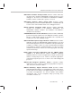
Table Of Contents
- Read This First
- Contents
- Figures
- Tables
- Examples
- Cautions
- Introduction
- Architectural Overview
- Central Processing Unit
- Memory and I/O Spaces
- Program Control
- Addressing Modes
- Assembly Language Instructions
- Instruction Set Summary
- How To Use the Instruction Descriptions
- Instruction Descriptions
- ABS
- ABS
- ADD
- ADD
- ADD
- ADD
- ADDC
- ADDC
- ADDS
- ADDS
- ADDT
- ADDT
- ADRK
- AND
- AND
- AND
- APAC
- APAC
- B
- BACC
- BANZ
- BANZ
- BCND
- BCND
- BIT
- BIT
- BITT
- BITT
- BLDD
- BLDD
- BLDD
- BLDD
- BLDD
- BLPD
- BLPD
- BLPD
- BLPD
- CALA
- CALL
- CC
- CC
- CLRC
- CLRC
- CMPL
- CMPR
- DMOV
- DMOV
- IDLE
- IN
- IN
- INTR
- LACC
- LACC
- LACC
- LACL
- LACL
- LACL
- LACT
- LACT
- LAR
- LAR
- LAR
- LDP
- LDP
- LPH
- LPH
- LST
- LST
- LST
- LST
- LT
- LT
- LTA
- LTA
- LTD
- LTD
- LTD
- LTP
- LTP
- LTS
- LTS
- MAC
- MAC
- MAC
- MAC
- MACD
- MACD
- MACD
- MACD
- MACD
- MAR
- MAR
- MPY
- MPY
- MPY
- MPYA
- MPYA
- MPYS
- MPYS
- MPYU
- MPYU
- NEG
- NEG
- NMI
- NOP
- NORM
- NORM
- NORM
- OR
- OR
- OR
- OUT
- OUT
- PAC
- POP
- POP
- POPD
- POPD
- PSHD
- PSHD
- PUSH
- RET
- RETC
- ROL
- ROR
- RPT
- RPT
- SACH
- SACH
- SACL
- SACL
- SAR
- SAR
- SBRK
- SETC
- SETC
- SFL
- SFR
- SFR
- SPAC
- SPH
- SPH
- SPL
- SPL
- SPLK
- SPLK
- SPM
- SQRA
- SQRA
- SQRS
- SQRS
- SST
- SST
- SUB
- SUB
- SUB
- SUB
- SUBB
- SUBB
- SUBC
- SUBC
- SUBS
- SUBS
- SUBT
- SUBT
- TBLR
- TBLR
- TBLR
- TBLW
- TBLW
- TBLW
- TRAP
- XOR
- XOR
- XOR
- ZALR
- ZALR
- On-Chip Peripherals
- Synchronous Serial Port
- Asynchronous Serial Port
- TMS320C209
- Register Summary
- TMS320C1x/C2x/C2xx/C5x Instruction Set Comparison
- Program Examples
- Submitting ROM Codes to TI
- Design Considerations for Using XDS510 Emulator
- E.1 Designing Your Target System’s Emulator Connector (14-Pin Header)
- E.2 Bus Protocol
- E.3 Emulator Cable Pod
- E.4 Emulator Cable Pod Signal Timing
- E.5 Emulation Timing Calculations
- E.6 Connections Between the Emulator and the Target System
- E.7 Physical Dimensions for the 14-Pin Emulator Connector
- E.8 Emulation Design Considerations
- Glossary
- Index

How to Use This Manual
iv
For this information: Look here:
Addressing modes (for addressing data
memory)
Chapter 6,
Addressing Modes
Assembly language instructions Chapter 7,
Assembly Language
Instructions
Assembly language instructions of
TMS320C1x, ’C2x, ’C2xx, and ’C5x
compared
Appendix B,
TMS320C1x/C2x/C2xx/C5x
Instruction Set Comparison
Boot loader Chapter 4,
Memory and I/O Spaces
Clock generator Chapter 8,
On-Chip Peripherals
CPU Chapter 3,
Central Processing Unit
Custom ROM from TI Appendix D,
Submitting ROM Codes
to TI
Emulator Appendix E,
Design Considerations for
Using XDS510 Emulator
Features Chapter 1,
Introduction
Chapter 2,
Architectural Overview
Input/output ports Chapter 4,
Memory and I/O Spaces
Interrupts Chapter 5,
Program Control
Memory configuration Chapter 4,
Memory and I/O Spaces
Memory interfacing Chapter 4,
Memory and I/O Spaces
On-chip peripherals Chapter 8,
On-Chip Peripherals
Pipeline Chapter 5,
Program Control
Program control Chapter 5,
Program Control
Program examples Appendix C,
Program Examples
Program-memory address generation Chapter 5,
Program Control
Registers summarized Appendix A,
Register Summary
Serial ports Chapter 9,
Synchronous Serial Port
Chapter 10,
Asynchronous Serial Port
Stack Chapter 5,
Program Control
Status registers Chapter 5,
Program Control
Timer Chapter 8,
On-Chip Peripherals
TMS320C209 differences and
similarities
Chapter 11,
TMS320C209
Wait-state generator Chapter 8,
On-Chip Peripherals