
User manual
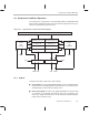
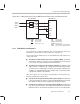

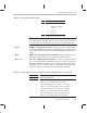
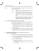
Table Of Contents
- Read This First
- Contents
- Figures
- Tables
- Examples
- Cautions
- Introduction
- Architectural Overview
- Central Processing Unit
- Memory and I/O Spaces
- Program Control
- Addressing Modes
- Assembly Language Instructions
- Instruction Set Summary
- How To Use the Instruction Descriptions
- Instruction Descriptions
- ABS
- ABS
- ADD
- ADD
- ADD
- ADD
- ADDC
- ADDC
- ADDS
- ADDS
- ADDT
- ADDT
- ADRK
- AND
- AND
- AND
- APAC
- APAC
- B
- BACC
- BANZ
- BANZ
- BCND
- BCND
- BIT
- BIT
- BITT
- BITT
- BLDD
- BLDD
- BLDD
- BLDD
- BLDD
- BLPD
- BLPD
- BLPD
- BLPD
- CALA
- CALL
- CC
- CC
- CLRC
- CLRC
- CMPL
- CMPR
- DMOV
- DMOV
- IDLE
- IN
- IN
- INTR
- LACC
- LACC
- LACC
- LACL
- LACL
- LACL
- LACT
- LACT
- LAR
- LAR
- LAR
- LDP
- LDP
- LPH
- LPH
- LST
- LST
- LST
- LST
- LT
- LT
- LTA
- LTA
- LTD
- LTD
- LTD
- LTP
- LTP
- LTS
- LTS
- MAC
- MAC
- MAC
- MAC
- MACD
- MACD
- MACD
- MACD
- MACD
- MAR
- MAR
- MPY
- MPY
- MPY
- MPYA
- MPYA
- MPYS
- MPYS
- MPYU
- MPYU
- NEG
- NEG
- NMI
- NOP
- NORM
- NORM
- NORM
- OR
- OR
- OR
- OUT
- OUT
- PAC
- POP
- POP
- POPD
- POPD
- PSHD
- PSHD
- PUSH
- RET
- RETC
- ROL
- ROR
- RPT
- RPT
- SACH
- SACH
- SACL
- SACL
- SAR
- SAR
- SBRK
- SETC
- SETC
- SFL
- SFR
- SFR
- SPAC
- SPH
- SPH
- SPL
- SPL
- SPLK
- SPLK
- SPM
- SQRA
- SQRA
- SQRS
- SQRS
- SST
- SST
- SUB
- SUB
- SUB
- SUB
- SUBB
- SUBB
- SUBC
- SUBC
- SUBS
- SUBS
- SUBT
- SUBT
- TBLR
- TBLR
- TBLR
- TBLW
- TBLW
- TBLW
- TRAP
- XOR
- XOR
- XOR
- ZALR
- ZALR
- On-Chip Peripherals
- Synchronous Serial Port
- Asynchronous Serial Port
- TMS320C209
- Register Summary
- TMS320C1x/C2x/C2xx/C5x Instruction Set Comparison
- Program Examples
- Submitting ROM Codes to TI
- Design Considerations for Using XDS510 Emulator
- E.1 Designing Your Target System’s Emulator Connector (14-Pin Header)
- E.2 Bus Protocol
- E.3 Emulator Cable Pod
- E.4 Emulator Cable Pod Signal Timing
- E.5 Emulation Timing Calculations
- E.6 Connections Between the Emulator and the Target System
- E.7 Physical Dimensions for the 14-Pin Emulator Connector
- E.8 Emulation Design Considerations
- Glossary
- Index

Controlling and Resetting the Port
9-8
9.3 Controlling and Resetting the Port
The synchronous serial port control register (SSPCR) controls the operation
of the synchronous serial port. To configure the serial port, a total of two writes
to the SSPCR are necessary:
1) Write your choices to the configuration bits and place the port in reset by
writing zeros to SSPCR bits XRST and RRST.
2) Write your choices to the configuration bits and take the port out of reset
by writing ones to bits XRST and RRST.
Note:
Set the DLB bit of the SSPCR to zero to disable digital loopback mode, which
is not normally used in serial transfers. See subsection 9.7.1,
Test Bits
, for
a description of digital loopback mode.
Make sure you write your configuration choices to the SSPCR during both
writes.
Figure 9–3 shows the 16-bit memory-mapped SSPCR. Following the figure is
a description of each of the bits.
Figure 9–3. Synchronous Serial Port Control Register (SSPCR)
— I/O-Space Address FFF1h
15 14 13 12
11 10 9 8
FREE SOFT TCOMP RFNE FT1 FT0 FR1 FR0
R/W–0 R/W–0 R–0 R–0 R/W–0 R/W–0 R/W–0 R/W–0
7 6 5 4
3 2 1 0
OVF IN0 XRST RRST TXM MCM FSM DLB
R–0 R–0 R/W–1 R/W–1 R/W–0 R/W–0 R/W–0 R/W–0
Note: R=Read access; W=Write access; value following dash (–) is value after reset.
Bits 15–14 FREE, SOFT. These bits are special emulation bits that determine the state
of the serial port clock when a breakpoint is encountered in the high-level lan-
guage debugger. If the FREE bit is set to 1, then, upon a breakpoint, the clock
continues to run (that is, free runs) and data is shifted out. In this case, SOFT
is a
don’t care
. If FREE = 0, then SOFT takes effect. The effects of FREE and
SOFT are summarized in Table 9–2. At reset, immediate stop mode is se-
lected (FREE = 0 and SOFT = 0).