
User manual
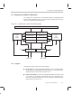

Table Of Contents
- Read This First
- Contents
- Figures
- Tables
- Examples
- Cautions
- Introduction
- Architectural Overview
- Central Processing Unit
- Memory and I/O Spaces
- Program Control
- Addressing Modes
- Assembly Language Instructions
- Instruction Set Summary
- How To Use the Instruction Descriptions
- Instruction Descriptions
- ABS
- ABS
- ADD
- ADD
- ADD
- ADD
- ADDC
- ADDC
- ADDS
- ADDS
- ADDT
- ADDT
- ADRK
- AND
- AND
- AND
- APAC
- APAC
- B
- BACC
- BANZ
- BANZ
- BCND
- BCND
- BIT
- BIT
- BITT
- BITT
- BLDD
- BLDD
- BLDD
- BLDD
- BLDD
- BLPD
- BLPD
- BLPD
- BLPD
- CALA
- CALL
- CC
- CC
- CLRC
- CLRC
- CMPL
- CMPR
- DMOV
- DMOV
- IDLE
- IN
- IN
- INTR
- LACC
- LACC
- LACC
- LACL
- LACL
- LACL
- LACT
- LACT
- LAR
- LAR
- LAR
- LDP
- LDP
- LPH
- LPH
- LST
- LST
- LST
- LST
- LT
- LT
- LTA
- LTA
- LTD
- LTD
- LTD
- LTP
- LTP
- LTS
- LTS
- MAC
- MAC
- MAC
- MAC
- MACD
- MACD
- MACD
- MACD
- MACD
- MAR
- MAR
- MPY
- MPY
- MPY
- MPYA
- MPYA
- MPYS
- MPYS
- MPYU
- MPYU
- NEG
- NEG
- NMI
- NOP
- NORM
- NORM
- NORM
- OR
- OR
- OR
- OUT
- OUT
- PAC
- POP
- POP
- POPD
- POPD
- PSHD
- PSHD
- PUSH
- RET
- RETC
- ROL
- ROR
- RPT
- RPT
- SACH
- SACH
- SACL
- SACL
- SAR
- SAR
- SBRK
- SETC
- SETC
- SFL
- SFR
- SFR
- SPAC
- SPH
- SPH
- SPL
- SPL
- SPLK
- SPLK
- SPM
- SQRA
- SQRA
- SQRS
- SQRS
- SST
- SST
- SUB
- SUB
- SUB
- SUB
- SUBB
- SUBB
- SUBC
- SUBC
- SUBS
- SUBS
- SUBT
- SUBT
- TBLR
- TBLR
- TBLR
- TBLW
- TBLW
- TBLW
- TRAP
- XOR
- XOR
- XOR
- ZALR
- ZALR
- On-Chip Peripherals
- Synchronous Serial Port
- Asynchronous Serial Port
- TMS320C209
- Register Summary
- TMS320C1x/C2x/C2xx/C5x Instruction Set Comparison
- Program Examples
- Submitting ROM Codes to TI
- Design Considerations for Using XDS510 Emulator
- E.1 Designing Your Target System’s Emulator Connector (14-Pin Header)
- E.2 Bus Protocol
- E.3 Emulator Cable Pod
- E.4 Emulator Cable Pod Signal Timing
- E.5 Emulation Timing Calculations
- E.6 Connections Between the Emulator and the Target System
- E.7 Physical Dimensions for the 14-Pin Emulator Connector
- E.8 Emulation Design Considerations
- Glossary
- Index

Components and Basic Operation
9-6
9.2.3 Interrupts
The synchronous serial port (SSP) has two hardware interrupts that let the pro-
cessor know when the FIFO buffers need to be serviced:
Transmit interrupts (XINTs) cause a branch to address 000Ah in program
space whenever the transmit-interrupt trigger condition is met. Set the trig-
ger condition by setting bits FT1 and FT0 in the SSPCR (see Table 9–3
on page 9-9). XINTs have a priority level of 8 (1 being highest).
Receive interrupts (RINTs) cause a branch to address 0008h in program
space whenever the receive-interrupt-trigger condition is met. The trigger
condition is selected by setting the FR1 and FR0 bits in the SSPCR (see
Table 9–4 on page 9-10). RINTs have a priority level of 7.
These are maskable interrupts controlled by the interrupt mask register (IMR)
and interrupt flag register (IFR).
Note:
To avoid a double interrupt from the SSP, clear the IFR bit (XINT or RINT)
in the corresponding interrupt service routine, just before returning from the
routine.
9.2.4 Basic Operation
Typically, transmitting a word through the serial port follows this four step
process:
1) Initialize the serial port to the desired configuration by writing to the
SSPCR.
2) Your software writes up to four words to the transmit FIFO buffer through
the SDTR.
3) The transmit FIFO buffer copies the earliest-written word to the transmit
shift register (XSR) when the XSR is empty.
4) The XSR shifts the data, bit-by-bit (MSB first), to the DX pin.
5) When the XSR empties, it signals the FIFO buffer, and then:
If the FIFO buffer is not empty, the process repeats from step 2.
If the FIFO buffer is empty (as specified by the FT1 and FT0 bits in the
SSPCR), it sends a transmit interrupt (XINT) to request more data,
and transmission stops.