
User manual
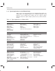
Table Of Contents
- Read This First
- Contents
- Figures
- Tables
- Examples
- Cautions
- Introduction
- Architectural Overview
- Central Processing Unit
- Memory and I/O Spaces
- Program Control
- Addressing Modes
- Assembly Language Instructions
- Instruction Set Summary
- How To Use the Instruction Descriptions
- Instruction Descriptions
- ABS
- ABS
- ADD
- ADD
- ADD
- ADD
- ADDC
- ADDC
- ADDS
- ADDS
- ADDT
- ADDT
- ADRK
- AND
- AND
- AND
- APAC
- APAC
- B
- BACC
- BANZ
- BANZ
- BCND
- BCND
- BIT
- BIT
- BITT
- BITT
- BLDD
- BLDD
- BLDD
- BLDD
- BLDD
- BLPD
- BLPD
- BLPD
- BLPD
- CALA
- CALL
- CC
- CC
- CLRC
- CLRC
- CMPL
- CMPR
- DMOV
- DMOV
- IDLE
- IN
- IN
- INTR
- LACC
- LACC
- LACC
- LACL
- LACL
- LACL
- LACT
- LACT
- LAR
- LAR
- LAR
- LDP
- LDP
- LPH
- LPH
- LST
- LST
- LST
- LST
- LT
- LT
- LTA
- LTA
- LTD
- LTD
- LTD
- LTP
- LTP
- LTS
- LTS
- MAC
- MAC
- MAC
- MAC
- MACD
- MACD
- MACD
- MACD
- MACD
- MAR
- MAR
- MPY
- MPY
- MPY
- MPYA
- MPYA
- MPYS
- MPYS
- MPYU
- MPYU
- NEG
- NEG
- NMI
- NOP
- NORM
- NORM
- NORM
- OR
- OR
- OR
- OUT
- OUT
- PAC
- POP
- POP
- POPD
- POPD
- PSHD
- PSHD
- PUSH
- RET
- RETC
- ROL
- ROR
- RPT
- RPT
- SACH
- SACH
- SACL
- SACL
- SAR
- SAR
- SBRK
- SETC
- SETC
- SFL
- SFR
- SFR
- SPAC
- SPH
- SPH
- SPL
- SPL
- SPLK
- SPLK
- SPM
- SQRA
- SQRA
- SQRS
- SQRS
- SST
- SST
- SUB
- SUB
- SUB
- SUB
- SUBB
- SUBB
- SUBC
- SUBC
- SUBS
- SUBS
- SUBT
- SUBT
- TBLR
- TBLR
- TBLR
- TBLW
- TBLW
- TBLW
- TRAP
- XOR
- XOR
- XOR
- ZALR
- ZALR
- On-Chip Peripherals
- Synchronous Serial Port
- Asynchronous Serial Port
- TMS320C209
- Register Summary
- TMS320C1x/C2x/C2xx/C5x Instruction Set Comparison
- Program Examples
- Submitting ROM Codes to TI
- Design Considerations for Using XDS510 Emulator
- E.1 Designing Your Target System’s Emulator Connector (14-Pin Header)
- E.2 Bus Protocol
- E.3 Emulator Cable Pod
- E.4 Emulator Cable Pod Signal Timing
- E.5 Emulation Timing Calculations
- E.6 Connections Between the Emulator and the Target System
- E.7 Physical Dimensions for the 14-Pin Emulator Connector
- E.8 Emulation Design Considerations
- Glossary
- Index

TMS320C2xx Generation
1-5
Introduction
1.2 TMS320C2xx Generation
Texas Instruments uses static CMOS integrated-circuit technology to fabricate
the TMS320C2xx DSPs. The architectural design of the ’C2xx is based on that
of the ’C5x. The operational flexibility and speed of the ’C2xx and ’C5x are a
result of an advanced, modified Harvard architecture (which has separate
buses for program and data memory), a multilevel pipeline, on-chip peripher-
als, on-chip memory, and a highly specialized instruction set. The ’C2xx per-
forms up to 40 MIPS (million instructions per second).
The ’C2xx generation offers the following benefits:
Enhanced TMS320 architectural design for increased performance and
versatility
Modular architectural design for fast development of additional spin-off
devices
Advanced IC processing technology for increased performance
Fast and easy performance upgrades for ’C1x and ’C2x source code,
which is upward compatible with ’C2xx source code
Enhanced instruction set for faster algorithms and for optimized high-level
language operation
New static design techniques for minimizing power consumption
Table 1–2 provides an overview of the basic features of the ’C2xx DSPs.
Table 1–2. ’C2xx Generation Summary
On-Chip Memory Serial Ports
Device
Cycle Time
(ns)
RAM ROM Flash Synch. Asynch. Timers Package
TMS320C203
25/35/50 544 1 1 1 100 TQFP
†
TMS320C204 25/35/50 544 4K 1 1 1 100 TQFP
†
TMS320F206 25/35/50 4.5K 32K 1 1 1 100 TQFP
†
TMS320C209 35/50 4.5K 4K – – 1 80 TQFP
†
†
TQFP = Thin quad flat pack