
User manual
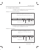
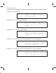

Table Of Contents
- Read This First
- Contents
- Figures
- Tables
- Examples
- Cautions
- Introduction
- Architectural Overview
- Central Processing Unit
- Memory and I/O Spaces
- Program Control
- Addressing Modes
- Assembly Language Instructions
- Instruction Set Summary
- How To Use the Instruction Descriptions
- Instruction Descriptions
- ABS
- ABS
- ADD
- ADD
- ADD
- ADD
- ADDC
- ADDC
- ADDS
- ADDS
- ADDT
- ADDT
- ADRK
- AND
- AND
- AND
- APAC
- APAC
- B
- BACC
- BANZ
- BANZ
- BCND
- BCND
- BIT
- BIT
- BITT
- BITT
- BLDD
- BLDD
- BLDD
- BLDD
- BLDD
- BLPD
- BLPD
- BLPD
- BLPD
- CALA
- CALL
- CC
- CC
- CLRC
- CLRC
- CMPL
- CMPR
- DMOV
- DMOV
- IDLE
- IN
- IN
- INTR
- LACC
- LACC
- LACC
- LACL
- LACL
- LACL
- LACT
- LACT
- LAR
- LAR
- LAR
- LDP
- LDP
- LPH
- LPH
- LST
- LST
- LST
- LST
- LT
- LT
- LTA
- LTA
- LTD
- LTD
- LTD
- LTP
- LTP
- LTS
- LTS
- MAC
- MAC
- MAC
- MAC
- MACD
- MACD
- MACD
- MACD
- MACD
- MAR
- MAR
- MPY
- MPY
- MPY
- MPYA
- MPYA
- MPYS
- MPYS
- MPYU
- MPYU
- NEG
- NEG
- NMI
- NOP
- NORM
- NORM
- NORM
- OR
- OR
- OR
- OUT
- OUT
- PAC
- POP
- POP
- POPD
- POPD
- PSHD
- PSHD
- PUSH
- RET
- RETC
- ROL
- ROR
- RPT
- RPT
- SACH
- SACH
- SACL
- SACL
- SAR
- SAR
- SBRK
- SETC
- SETC
- SFL
- SFR
- SFR
- SPAC
- SPH
- SPH
- SPL
- SPL
- SPLK
- SPLK
- SPM
- SQRA
- SQRA
- SQRS
- SQRS
- SST
- SST
- SUB
- SUB
- SUB
- SUB
- SUBB
- SUBB
- SUBC
- SUBC
- SUBS
- SUBS
- SUBT
- SUBT
- TBLR
- TBLR
- TBLR
- TBLW
- TBLW
- TBLW
- TRAP
- XOR
- XOR
- XOR
- ZALR
- ZALR
- On-Chip Peripherals
- Synchronous Serial Port
- Asynchronous Serial Port
- TMS320C209
- Register Summary
- TMS320C1x/C2x/C2xx/C5x Instruction Set Comparison
- Program Examples
- Submitting ROM Codes to TI
- Design Considerations for Using XDS510 Emulator
- E.1 Designing Your Target System’s Emulator Connector (14-Pin Header)
- E.2 Bus Protocol
- E.3 Emulator Cable Pod
- E.4 Emulator Cable Pod Signal Timing
- E.5 Emulation Timing Calculations
- E.6 Connections Between the Emulator and the Target System
- E.7 Physical Dimensions for the 14-Pin Emulator Connector
- E.8 Emulation Design Considerations
- Glossary
- Index

Instruction Set Summary
7-2
7.1 Instruction Set Summary
This section provides a summary of the instruction set in six tables (Table 7–1
to Table 7–6) according to the following functional headings:
Accumulator, arithmetic, and logic instructions (see Table 7–1 on page
7-4)
Auxiliary register and data page pointer instructions (see Table 7–2 on
page 7-7)
TREG, PREG, and multiply instructions (see Table 7–3 on page 7-7)
Branch instructions (see Table 7–4 on page 7-8)
Control instructions (see Table 7–5 on page 7-9)
I/O and memory operations (see Table 7–6 on page 7-10)
Within each table, the instructions are arranged alphabetically. The number of
words that an instruction occupies in program memory is specified in column
three of each table; the number of cycles that an instruction requires to execute
is in column four. All instructions are assumed to be executed from internal
program memory (RAM) and internal data dual-access memory. The cycle
timings are for single-instruction execution, not for repeat mode. Additional
information about each instruction is presented in the individual instruction
descriptions in Section 7.2.
For your reference, here are definitions of the symbols used in these six sum-
mary tables:
ACC The accumulator
AR Auxiliary register
ARX A 3-bit value used in the LAR and SAR instructions to desig-
nate which auxiliary register will be loaded (LAR) or have its
contents stored (SAR)
BITX A 4-bit value (called the bit code) that determines which bit of
a designated data memory value will be tested by the BIT
instruction
CM A 2-bit value. The CMPR instruction performs a comparison
specified by the value of CM:
If CM = 00, test whether current AR = AR0
If CM = 01, test whether current AR < AR0
If CM = 10, test whether current AR > AR0
If CM = 11, test whether current AR ≠ AR0