
User manual

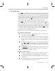
Table Of Contents
- Read This First
- Contents
- Figures
- Tables
- Examples
- Cautions
- Introduction
- Architectural Overview
- Central Processing Unit
- Memory and I/O Spaces
- Program Control
- Addressing Modes
- Assembly Language Instructions
- Instruction Set Summary
- How To Use the Instruction Descriptions
- Instruction Descriptions
- ABS
- ABS
- ADD
- ADD
- ADD
- ADD
- ADDC
- ADDC
- ADDS
- ADDS
- ADDT
- ADDT
- ADRK
- AND
- AND
- AND
- APAC
- APAC
- B
- BACC
- BANZ
- BANZ
- BCND
- BCND
- BIT
- BIT
- BITT
- BITT
- BLDD
- BLDD
- BLDD
- BLDD
- BLDD
- BLPD
- BLPD
- BLPD
- BLPD
- CALA
- CALL
- CC
- CC
- CLRC
- CLRC
- CMPL
- CMPR
- DMOV
- DMOV
- IDLE
- IN
- IN
- INTR
- LACC
- LACC
- LACC
- LACL
- LACL
- LACL
- LACT
- LACT
- LAR
- LAR
- LAR
- LDP
- LDP
- LPH
- LPH
- LST
- LST
- LST
- LST
- LT
- LT
- LTA
- LTA
- LTD
- LTD
- LTD
- LTP
- LTP
- LTS
- LTS
- MAC
- MAC
- MAC
- MAC
- MACD
- MACD
- MACD
- MACD
- MACD
- MAR
- MAR
- MPY
- MPY
- MPY
- MPYA
- MPYA
- MPYS
- MPYS
- MPYU
- MPYU
- NEG
- NEG
- NMI
- NOP
- NORM
- NORM
- NORM
- OR
- OR
- OR
- OUT
- OUT
- PAC
- POP
- POP
- POPD
- POPD
- PSHD
- PSHD
- PUSH
- RET
- RETC
- ROL
- ROR
- RPT
- RPT
- SACH
- SACH
- SACL
- SACL
- SAR
- SAR
- SBRK
- SETC
- SETC
- SFL
- SFR
- SFR
- SPAC
- SPH
- SPH
- SPL
- SPL
- SPLK
- SPLK
- SPM
- SQRA
- SQRA
- SQRS
- SQRS
- SST
- SST
- SUB
- SUB
- SUB
- SUB
- SUBB
- SUBB
- SUBC
- SUBC
- SUBS
- SUBS
- SUBT
- SUBT
- TBLR
- TBLR
- TBLR
- TBLW
- TBLW
- TBLW
- TRAP
- XOR
- XOR
- XOR
- ZALR
- ZALR
- On-Chip Peripherals
- Synchronous Serial Port
- Asynchronous Serial Port
- TMS320C209
- Register Summary
- TMS320C1x/C2x/C2xx/C5x Instruction Set Comparison
- Program Examples
- Submitting ROM Codes to TI
- Design Considerations for Using XDS510 Emulator
- E.1 Designing Your Target System’s Emulator Connector (14-Pin Header)
- E.2 Bus Protocol
- E.3 Emulator Cable Pod
- E.4 Emulator Cable Pod Signal Timing
- E.5 Emulation Timing Calculations
- E.6 Connections Between the Emulator and the Target System
- E.7 Physical Dimensions for the 14-Pin Emulator Connector
- E.8 Emulation Design Considerations
- Glossary
- Index

Power-Down Mode
5-37
Program Control
5.8.2 Termination of Power-Down During a HOLD Operation
One of the necessary steps in the HOLD operation is the execution of an IDLE
instruction (see Section 4.7,
Direct Memory Access Using The HOLD Opera-
tion
, on page 4-27) . There are unique characteristics of the HOLD operation
that affect how the IDLE state can be exited.
Before performing a HOLD operation, your program must write a 0 to the
MODE bit (bit 4 of the interrupt control register, ICR). This makes the
HOLD
/INT1 pin both negative- and positive-edge sensitive. A
falling
edge on
HOLD
/INT1 will cause the CPU to branch to the interrupt service routine, which
initiates the HOLD operation with an IDLE instruction. A subsequent
rising
edge on HOLD/INT1 can take the CPU out of the IDLE state and end the HOLD
operation. This rising-edge interrupt does
not
cause the CPU to branch to the
interrupt service routine.
The recommended software logic for the HOLD operation is described in Sec-
tion 4.7,
Direct Memory Access Using the HOLD Operation
, on page 4-27.
During a HOLD operation, there are only three valid methods for taking the
CPU out of the IDLE state:
Causing a rising edge on the HOLD/INT1 pin.
Asserting a system reset at the reset pin.
Asserting the nonmaskable interrupt NMI at the NMI pin.
If you use reset or NMI
, the CPU will immediately execute the corresponding
interrupt service routine. In addition, if you use reset, the contents of some reg-
isters will be changed. For more information about exiting a HOLD operation
with reset or NMI
, see Section 4.7,
Direct Memory Access Using The HOLD
Operation
, on page 4-27.