
User manual
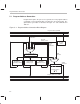

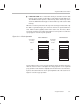
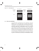
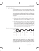

Table Of Contents
- Read This First
- Contents
- Figures
- Tables
- Examples
- Cautions
- Introduction
- Architectural Overview
- Central Processing Unit
- Memory and I/O Spaces
- Program Control
- Addressing Modes
- Assembly Language Instructions
- Instruction Set Summary
- How To Use the Instruction Descriptions
- Instruction Descriptions
- ABS
- ABS
- ADD
- ADD
- ADD
- ADD
- ADDC
- ADDC
- ADDS
- ADDS
- ADDT
- ADDT
- ADRK
- AND
- AND
- AND
- APAC
- APAC
- B
- BACC
- BANZ
- BANZ
- BCND
- BCND
- BIT
- BIT
- BITT
- BITT
- BLDD
- BLDD
- BLDD
- BLDD
- BLDD
- BLPD
- BLPD
- BLPD
- BLPD
- CALA
- CALL
- CC
- CC
- CLRC
- CLRC
- CMPL
- CMPR
- DMOV
- DMOV
- IDLE
- IN
- IN
- INTR
- LACC
- LACC
- LACC
- LACL
- LACL
- LACL
- LACT
- LACT
- LAR
- LAR
- LAR
- LDP
- LDP
- LPH
- LPH
- LST
- LST
- LST
- LST
- LT
- LT
- LTA
- LTA
- LTD
- LTD
- LTD
- LTP
- LTP
- LTS
- LTS
- MAC
- MAC
- MAC
- MAC
- MACD
- MACD
- MACD
- MACD
- MACD
- MAR
- MAR
- MPY
- MPY
- MPY
- MPYA
- MPYA
- MPYS
- MPYS
- MPYU
- MPYU
- NEG
- NEG
- NMI
- NOP
- NORM
- NORM
- NORM
- OR
- OR
- OR
- OUT
- OUT
- PAC
- POP
- POP
- POPD
- POPD
- PSHD
- PSHD
- PUSH
- RET
- RETC
- ROL
- ROR
- RPT
- RPT
- SACH
- SACH
- SACL
- SACL
- SAR
- SAR
- SBRK
- SETC
- SETC
- SFL
- SFR
- SFR
- SPAC
- SPH
- SPH
- SPL
- SPL
- SPLK
- SPLK
- SPM
- SQRA
- SQRA
- SQRS
- SQRS
- SST
- SST
- SUB
- SUB
- SUB
- SUB
- SUBB
- SUBB
- SUBC
- SUBC
- SUBS
- SUBS
- SUBT
- SUBT
- TBLR
- TBLR
- TBLR
- TBLW
- TBLW
- TBLW
- TRAP
- XOR
- XOR
- XOR
- ZALR
- ZALR
- On-Chip Peripherals
- Synchronous Serial Port
- Asynchronous Serial Port
- TMS320C209
- Register Summary
- TMS320C1x/C2x/C2xx/C5x Instruction Set Comparison
- Program Examples
- Submitting ROM Codes to TI
- Design Considerations for Using XDS510 Emulator
- E.1 Designing Your Target System’s Emulator Connector (14-Pin Header)
- E.2 Bus Protocol
- E.3 Emulator Cable Pod
- E.4 Emulator Cable Pod Signal Timing
- E.5 Emulation Timing Calculations
- E.6 Connections Between the Emulator and the Target System
- E.7 Physical Dimensions for the 14-Pin Emulator Connector
- E.8 Emulation Design Considerations
- Glossary
- Index

Conditional Branches, Calls, and Returns
5-11
Program Control
Group 2. You can select up to three conditions. Each of these conditions
must be from a different category (A, B, or C); you cannot have two condi-
tions from the same category. For example, you can test TC, C, and BIO
at the same time, but you cannot test C and NC at the same time.
Table 5–4. Groupings of Conditions
Group 1 Group 2
Category A Category B Category A Category B Category C
EQ OV TC C BIO
NEQ NOV NTC NC
LT
LEQ
GT
GEQ
5.4.2 Stabilization of Conditions
A conditional instruction must be able to test the most recent values of the sta-
tus bits. Therefore, the conditions cannot be considered stable until the fourth,
or execution, stage of the pipeline, one cycle after the previous instruction has
been executed. The pipeline controller stops the decoding of any instructions
following the conditional instruction until the conditions are stable.
5.4.3 Conditional Branches
A branch instruction transfers program control to any location in program
memory. Conditional branch instructions are executed only when one or more
user-specified conditions are met (see Table 5–3 on page 5-10). If all the
conditions are met, the PC is loaded with the second word of the branch
instruction, which contains the address to branch to, and execution continues
at this address.
By the time the conditions have been tested, the two instruction words follow-
ing the conditional branch instruction have already been fetched in the pipe-
line. If all the conditions are met, these two instruction words are flushed from
the pipeline so that they are not executed, and then execution continues at the
branched-to address. If the conditions are
not
met, the two instruction words
are executed instead of the branch. Because conditional branches use condi-
tions determined by the execution of the previous instructions, a conditional
branch takes one more cycle than an unconditional one.