
User manual
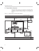


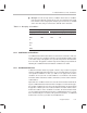
Table Of Contents
- Read This First
- Contents
- Figures
- Tables
- Examples
- Cautions
- Introduction
- Architectural Overview
- Central Processing Unit
- Memory and I/O Spaces
- Program Control
- Addressing Modes
- Assembly Language Instructions
- Instruction Set Summary
- How To Use the Instruction Descriptions
- Instruction Descriptions
- ABS
- ABS
- ADD
- ADD
- ADD
- ADD
- ADDC
- ADDC
- ADDS
- ADDS
- ADDT
- ADDT
- ADRK
- AND
- AND
- AND
- APAC
- APAC
- B
- BACC
- BANZ
- BANZ
- BCND
- BCND
- BIT
- BIT
- BITT
- BITT
- BLDD
- BLDD
- BLDD
- BLDD
- BLDD
- BLPD
- BLPD
- BLPD
- BLPD
- CALA
- CALL
- CC
- CC
- CLRC
- CLRC
- CMPL
- CMPR
- DMOV
- DMOV
- IDLE
- IN
- IN
- INTR
- LACC
- LACC
- LACC
- LACL
- LACL
- LACL
- LACT
- LACT
- LAR
- LAR
- LAR
- LDP
- LDP
- LPH
- LPH
- LST
- LST
- LST
- LST
- LT
- LT
- LTA
- LTA
- LTD
- LTD
- LTD
- LTP
- LTP
- LTS
- LTS
- MAC
- MAC
- MAC
- MAC
- MACD
- MACD
- MACD
- MACD
- MACD
- MAR
- MAR
- MPY
- MPY
- MPY
- MPYA
- MPYA
- MPYS
- MPYS
- MPYU
- MPYU
- NEG
- NEG
- NMI
- NOP
- NORM
- NORM
- NORM
- OR
- OR
- OR
- OUT
- OUT
- PAC
- POP
- POP
- POPD
- POPD
- PSHD
- PSHD
- PUSH
- RET
- RETC
- ROL
- ROR
- RPT
- RPT
- SACH
- SACH
- SACL
- SACL
- SAR
- SAR
- SBRK
- SETC
- SETC
- SFL
- SFR
- SFR
- SPAC
- SPH
- SPH
- SPL
- SPL
- SPLK
- SPLK
- SPM
- SQRA
- SQRA
- SQRS
- SQRS
- SST
- SST
- SUB
- SUB
- SUB
- SUB
- SUBB
- SUBB
- SUBC
- SUBC
- SUBS
- SUBS
- SUBT
- SUBT
- TBLR
- TBLR
- TBLR
- TBLW
- TBLW
- TBLW
- TRAP
- XOR
- XOR
- XOR
- ZALR
- ZALR
- On-Chip Peripherals
- Synchronous Serial Port
- Asynchronous Serial Port
- TMS320C209
- Register Summary
- TMS320C1x/C2x/C2xx/C5x Instruction Set Comparison
- Program Examples
- Submitting ROM Codes to TI
- Design Considerations for Using XDS510 Emulator
- E.1 Designing Your Target System’s Emulator Connector (14-Pin Header)
- E.2 Bus Protocol
- E.3 Emulator Cable Pod
- E.4 Emulator Cable Pod Signal Timing
- E.5 Emulation Timing Calculations
- E.6 Connections Between the Emulator and the Target System
- E.7 Physical Dimensions for the 14-Pin Emulator Connector
- E.8 Emulation Design Considerations
- Glossary
- Index

Conditional Branches, Calls, and Returns
5-10
5.4 Conditional Branches, Calls, and Returns
The ’C2xx provides branch, call, and return instructions that will execute only
if one or more conditions are met. You specify the conditions as operands of
the conditional instruction. Table 5–3 lists the conditions that you can use with
these instructions and their corresponding operand symbols.
Table 5–3. Conditions for Conditional Calls and Returns
Operand
Symbol
Condition Description
EQ ACC = 0 Accumulator equal to zero
NEQ ACC ≠ 0 Accumulator not equal to zero
LT ACC < 0 Accumulator less than zero
LEQ ACC 0 Accumulator less than or equal to zero
GT ACC > 0 Accumulator greater than zero
GEQ ACC 0 Accumulator greater than or equal to zero
C C = 1 Carry bit set to 1
NC C = 0 Carry bit cleared to 0
OV OV = 1 Accumulator overflow detected
NOV OV = 0 No accumulator overflow detected
BIO BIO low BIO pin is low
TC TC = 1 Test/control flag set to 1
NTC TC = 0 Test/control flag cleared to 0
5.4.1 Using Multiple Conditions
Multiple conditions can be listed as operands of the conditional instructions.
If multiple conditions are listed, all conditions must be met for the instruction
to execute. Note that only certain combinations of conditions are meaningful.
See Table 5–4. For each combination, the conditions must be selected from
Group 1 and Group 2 as follows:
Group 1. You can select up to two conditions. Each of these conditions
must be from a different category (A or B); you cannot have two conditions
from the same category. For example, you can test EQ and OV at the same
time, but you cannot test GT and NEQ at the same time.