
Datasheet


Table Of Contents
- FEATURES
- DESCRIPTION
- PIN CONNECTIONS
- ABSOLUTE MAXIMUM RATINGS
- DC ELECTRICAL CHARACTERISTICS
- VFC CHARACTERISTICS
- REG CHARACTERISTICS
- SMBus AC SPECIFICATIONS
- HDQ16 AC SPECIFICATIONS
- FUNCTIONAL DESCRIPTION
- General Operation
- Measurements
- Current
- Temperature
- GAS GAUGE OPERATION
- MAIN GAS GAUGE REGISTERS
- Self-Discharge
- Light Discharge or Suspend Current Compensation
- Midrange Capacity Corrections
- Charge Control
- Display Port
- Secondary Protection for Li-ion
- Low-Power Storage Mode
- Device Reset
- COMMUNICATION
- SMBus
- SMBus Protocol
- SMBus Packet Error Checking
- PEC Protocol
- PEC Calculation
- PEC Enable in Master Mode
- SMBus On and Off State
- HDQ16
- Command Codes
- ManufacturerAccess() (0x00); [0x00–0x01]
- RemainingCapacityAlarm() (0x01); [0x01]
- RemainingTimeAlarm() (0x02); [0x02]
- BatteryMode() (0x03); [0x03]
- AtRate() (0x04); [0x04]
- AtRateTimeToFull() (0x05);[0x05]
- AtRateTimeToEmpty() (0x06); [0x06]
- AtRateOK() (0x07); [0x07]
- Temperature() (0x08); [0x08]
- Voltage() (0x09); [0x09]
- Current() (0x0a); [0x0a]
- AverageCurrent() (0x0b); [0x0b]
- MaxError() (0x0c); [0x0c]
- RelativeStateOfCharge() (0x0d); [0x0d]
- AbsoluteStateOfCharge()(0x0e); [0x0e]
- RemainingCapacity() (0x0f); [0x0f]
- FullChargeCapacity() (0x10); [0x10]
- RunTimeToEmpty() (0x11); [0x11]
- AverageTimeToEmpty() (0x12); [0x12]
- AverageTimeToFull() (0x13); [0x13]
- ChargingCurrent() (0x14); [0x14]
- ChargingVoltage() (0x15); [0x15]
- BatteryStatus()(0x16); [0x16]
- CycleCount()(0x17); [0x17]
- DesignCapacity() (0x18); [0x18]
- DesignVoltage() (0x19); [0x19]
- SpecificationInfo() (0x1a); [0x1a]
- ManufactureDate() (0x1b); [0x1b]
- SerialNumber() (0x1c); [0x1c]
- ManufacturerName() (0x20); [0x20–0x2a]
- DeviceName() (0x21); [0x28–0x2b]
- DeviceChemistry() (0x22); [0x30–0x32]
- ManufacturerData() (0x23); [0x38–0x3a]
- Pack Status and Pack Configuration (0x2f); [0x2f]
- OCE
- EDV2
- EINT
- VDQ
- COK
- DOK
- CVOV
- CVUV
- VCELL4–VCELL1 (0x3c–0x3f); [0x3c–0x3f]
- EEPROM
- EEPROM Programming
- Fundamental Parameters
- Cell Characteristics
- Charge Limits and Termination Techniques
- Overvoltage
- Charging Current
- Charge Suspension
- FULLY_CHARGED Bit Clear Threshold
- Fast Charge Termination Percentage
- Cycle Count Threshold
- ΔT/Δt Rate Programming
- ΔT/Δt Holdoff Timer Programming
- Current Taper Termination Characteristics
- PACK OPTIONS
- DMODE
- SEAL
- CSYNC
- CEDV
- VCOR
- CHEM
- LCC0 and LCC1
- Remaining Time and Capacity Alarms
- Secondary Protection Limits for Li-Ion
- Miscellaneous Options
- NE1
- SOT
- HIT
- Cycle Count Initialization
- Control Modes
- NDF
- HPE
- CPE
- LED
- SC
- SM
- MEASUREMENT CALIBRATION
- CONSTANTS AND STRING DATA
- REVISION HISTORY
bq2060A
www.ti.com
SLUS500D –OCTOBER 2001– REVISED OCTOBER 2011
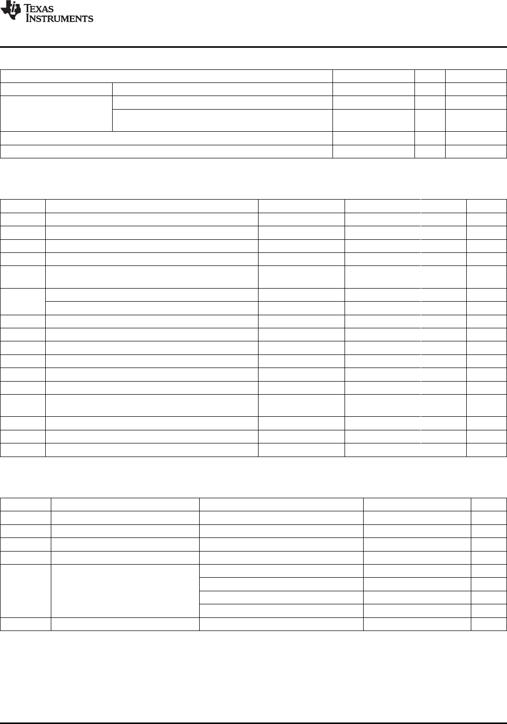
ABSOLUTE MAXIMUM RATINGS
MIN MAX UNIT NOTES
Supply voltage, V
CC
Relative to V
SS
–0.3 6 V
HDQ16, SMBC, SMBD relative to V
SS
–0.3 6 V
Input Voltage, V
IN
V
SS
– 0.3
All other pins V
CC
+ 0.3 V
to
Operating temperature, T
OPR
–20 70 °C Commercial
Junction temperature, T
J
–40 125 °C
DC ELECTRICAL CHARACTERISTICS
V
CC
= 2.7 V to 3.7 V, T
OPR
= –20°C to 70°C, unless otherwise noted
SYMBOL PARAMETER TEST CONDITIONS MIN TYP MAX UNIT
V
CC
Supply voltage 2.7 3.3 3.7 V
I
CC
Operating current V
OUT
inactive 180 235 µA
I
SLP
Low-power storage mode current 1.5 V < V
CC
< 3.7 V 5 10 µA
I
LVOUT
V
OUT
leakage current V
OUT
inactive –0.2 0.2 µA
V
OUT
active,
I
VOUT
V
OUT
source current –5 mA
V
CC
– 0.6 V
Output voltage low: LED1–LED5, CFC,DFC I
OLS
= 5 mA 0.4 V
V
OLS
Output voltage low: THON, CVON I
OLS
= 5 mA 0.36 V
V
IL
Input voltage low DISP –0.3 0.8 V
V
IH
Input voltage high DISP 2 V
CC
+ 0.3 V
V
OL
Output voltage low SMBC, SMBD, HDQ16, ESCL, ESDA I
OL
= 1 mA 0.4 V
V
ILS
Input voltage low SMBC, SMBD, HDQ16, ESCL, ESDA –0.3 0.8 V
V
IHS
Input voltage high SMBC, SMBD, HDQ16, ESCL, ESDA 1.7 6.0 V
V
AI
Input voltage range VCELL1–4, TS, SRC V
SS
– 0.3 1.25 V
V
RBI
> 3 V,
I
RB
RBI data-retention input current 10 50 nA
V
CC
< 2 V
V
RBI
RBI data-retention voltage 1.3 V
Z
AI1
Input impedance: SR1, SR2 0–1.25 V 10 MΩ
Z
AI2
Input impedance: VCELL1–4, TS, SRC 0–1.25 V 5 MΩ
VFC CHARACTERISTICS
V
CC
= 3.1 to 3.5 V, T
OPR
= –0°C to 70°C, unless otherwise noted
SYMBOL PARAMETER TEST CONDITIONS MIN TYP MAX UNIT
V
SR
Input voltage range, V
SR2
and V
SR1
V
SR
= V
SR2
– V
SR1
–0.25 +0.25 V
V
SROS
V
SR
input offset VSR2 = V
SR1
, auto-correction disabled –250 –50 250 µV
V
SRCOS
Calibrated offset –16 +16 µV
RM
VCO
Supply voltage gain coefficient
(1)
V
CC
= 3.3 V 0.8 1.2 %/V
Slope for T
OPR
= –20°C to 70°C –0.09 +0.09 %/°C
Total deviation T
OPR
= –20°C to 70°C –1.6% 0.1%
RM
TCO
Temperature gain coefficient
(1)
Slope for T
OPR
= –0°C to 50°C –0.05 +0.05 %/°C
Total deviation T
OPR
= –0°C to 50°C –0.6% 0.1%
INL Integral nonlinearity error T
OPR
= 0°C–50°C 0.21%
(1) RM
(TCO)
total deviation is from the nominal gain at 25°C.
Copyright © 2001–2011, Texas Instruments Incorporated Submit Documentation Feedback 3
Product Folder Link(s): bq2060A