
Datasheet


n
Fast charge termination
n
Maintenance charging
n
Charge regulation
Charge Algorithms
Three charge algorithms are available in the bq2031:
n
Two-Step Voltage
n
Two-Step Current
n
Pulsed Current
The state transitions for these algorithms are described
in Table 1 and are shown graphically in Figures 2
through 4. The user selects a charge algorithm by con
-
figuring pins QSEL and TSEL.
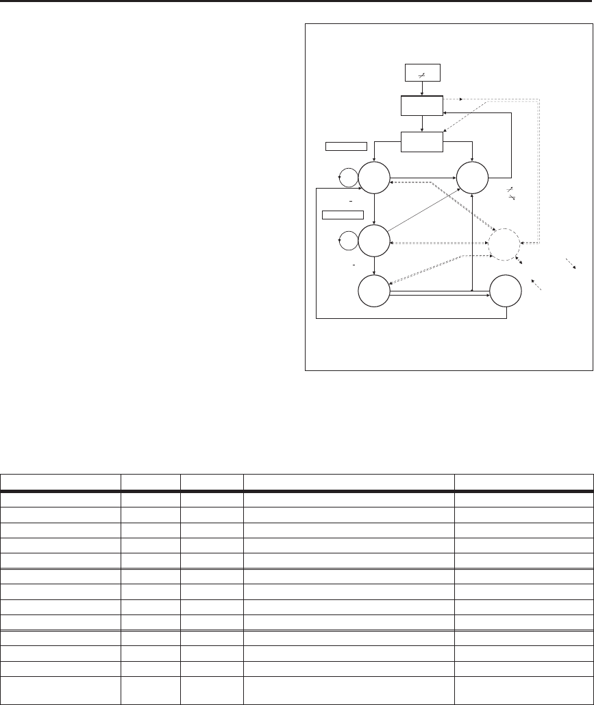
Charge Qualification
The bq2031 starts a charge cycle when power is applied
while a battery is present or when a battery is inserted.
Figure 1 shows the state diagram for pre-charge qualifi-
cation and temperature monitoring. The bq2031 first
checks that the battery temperature is within the al-
lowed, user-configurable range. If the temperature is
out-of-range (or the thermistor is missing), the bq2031
enters the Charge Pending state and waits until the bat-
tery temperature is within the allowed range. Charge
Pending is annunciated by LED
3
flashing.
3
bq2031
Algorithm/State QSEL TSEL Conditions MOD Output
Two-Step Voltage
L H/L
Note 1
--
Fast charge, phase 1 while V
BAT
<V
BLK
,I
SNS
=I
MAX
Current regulation
Fast charge, phase 2 while I
SNS
>I
MIN
,V
BAT
=V
BLK
Voltage regulation
Primary termination I
SNS
=I
MIN
Maintenance V
BAT
=V
FLT
Voltage regulation
Two-Step Current
HL - -
Fast charge while V
BAT
<V
BLK
,I
SNS
=I
MAX
Current regulation
Primary termination V
BAT
=V
BLK
or
∆
2
V < -8mV
Note 2
Maintenance I
SNS
pulsed to average I
FLT
Fixed pulse current
Pulsed Current
HH - -
Fast charge while V
BAT
<V
BLK
,I
SNS
=I
MAX
Current regulation
Primary termination V
BAT
=V
BLK
Maintenance
I
SNS
=I
MAX
after V
BAT
=V
FLT
;
I
SNS
= 0 after V
BAT
=V
BLK
Hysteretic pulsed
current
Notes: 1. May be high or low, but do not float.
2. A Unitrode proprietary algorithm for accumulating successive differences between samples of V
BAT
.
Table 1. bq2031 Charging Algorithms
Chip On
V
CC
4.5V
Temperature
Checks On
Battery
Status?
Temperature
in Range
Temperature Out
of Range or
Thermistor Absent
Voltage
Regulation
@ V
FLT
+
0.25V
Bulk
Charge
Fault
LED3 = 1
MOD = 0
Charge
Pending
LED3 Flash
MOD = 0
Current
Regulation
@I
COND
Temperature Out
of Range or
Thermistor Absent
Temperature In
Range, Return
to Original State
V
CELL
< V
LCO
or
V
CELL
> V
HCO
V
CELL
V
LCO or
Fail:
t = t
QT1
or
V
CELL
> V
HCO
Present
V
LCO
< V
CELL
< V
HCO
I
SNS
< I
COND
V
CELL
< V
MIN
FG203101.eps
Test 1
V
CELL
V
HCO
PASS: I
SNS
I
COND
>
Test 2
PASS: V
CELL
V
MIN
>
Fast
Charge
V
CELL
< V
MIN
Termination
Fail:
t = t
QT2
or
V
CELL
< V
LCO or
V
CELL
> V
HCO
Absent
V
CELL
< V
LCO
or
V
CELL
> V
HCO
Figure 1. Cycle Start/Battery
Qualification State Diagram