C2000 LED BoosterPack User's Guide Literature Number: SPRUHH9 July 2012
Contents 1 ..................................................................................... 4 .................................................................................................................. 4 Getting Familiar With the Kit ................................................................................................. 5 2.1 Kit Contents .............................................................................................................. 5 2.2 Kit Specifications ............
www.ti.com List of Figures ................................................................................ 1 LED BoosterPack (BOOSTXL-C2KLED) 2 Lighting System Topology ................................................................................................. 5 3 LED BoosterPack Circuit Diagram ........................................................................................ 6 4 LED BoosterPack Subsytem Locations .......................................................................
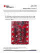
User's Guide SPRUHH9 – July 2012 C2000 LED BoosterPack 1 C2000™ LED BoosterPack Overview 1.1 Overview The LED BoosterPack is an add-on board designed to fit the C2000 LaunchPad and the other 40-pin based LaunchPads. This BoosterPack provides users with a way to accurately control a series of LED strings while efficiently controlling the power stages needed to make the LEDs work.
Getting Familiar With the Kit www.ti.com 2 Getting Familiar With the Kit 2.1 Kit Contents The kit consists of: • LED BoosterPack • AC/DC Power Adapter (12 V 1A) • Quick Start Guide 2.2 Kit Specifications The LED BoosterPack has the following specifications: • Power Input: – 6 V minimum @ 1.
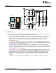
Hardware Overview www.ti.com Vin-12v Boost V-boost1 + 1A V-boost2 F28027 I-Led1 I-Led2 CPU 32 bit DSP core 60 MHz 3V3 Comms 2 IC SPI UART + 1B ADC 12 bit 4.6 MSPS Vref I-Led8 V-boost1 V-boost6 V-sepic1 V-sepic2 PWM1(HR) 1A / 1B PWM2(HR) 2A / 2B PWM3(HR) 3A / 3B PWM4(HR) 4A / 4B V-boost6 I-Led6 I-Led2 I-Led1 + 3B Figure 3. LED BoosterPack Circuit Diagram 3.1 Subsystems The LED BoosterPack board is divided into functional groups referred to as subsystems.
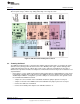
Hardware Overview www.ti.com Figure 4 illustrates the position of these subsystems on the board. The use of a subsystem approach, for different power stages, enables easy debug and testing of one stage at a time. Figure 4. LED BoosterPack Subsytem Locations 3.
Getting Started • 3.3 www.ti.com Isolated/Standalone – Used to protect the host PC while debugging the application, which may present dangerous voltages to a PC or when the user wants to run a standalone application with a single supply. Power for the entire system (both LaunchPad and LED BoosterPack) is supplied from the 12 V AC/DC wall adapter. The USB can be optionally connected if the user wants to debug the application; in this case, power for the emulator is supplied via USB.
Getting Started www.ti.com 4.1.2 Software Setup for PC GUI Demo The GUI for evaluating this kit is named LED_BOOST_PC_GUI.exe and can be found in the C2000 LaunchPad controlSUITE™ package. This GUI is all the software necessary to do a quick evaluation of this kit. To explore deeper, the underlying reference software can be found within controlSUITE. NOTE: The GUI requires Microsoft® .NET framework 3.0 to run. Please ensure that this software is installed prior to running this program.
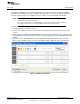
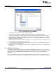
Getting Started www.ti.com 5. Click Setup Connection and make sure the baud rate is set to 57600 and that the Boot on Connect box is unchecked. Figure 6. GUI Setup Connections Window 6. Select the serial COM port. This can be found by going to: Control Panel → System → Hardware tab → Device Manager → Ports(COM and LPT) Look for the COM port that is named USB Serial Port (or similar) and note the number. Select this COM port in the Setup Connection window and click OK to close the window.
Getting Started www.ti.com Figure 7. LED BoosterPack With C2000 LaunchPad and MSP430 Capacitive Touch BoosterPack 4.2.1 Hardware Setup for Capacitive Touch Demo Perform or verify the following steps to prepare the LED BoosterPack for use with the MSP430 Capacitive Touch BoosterPack. 1. Verify the following jumper and switch settings on the LED BoosterPack: (a) A jumper is not placed on J2. (b) A jumper is not placed on J8. (c) The switch S1 is in the up position. 2.
Hardware Resource Mapping www.ti.com 4.2.2 Software Setup for Capacitive Touch Demo 1. Start Code Composer Studio version 5. 2. In the TI Resource Explorer, look for an entry called controlSUITE and expand the Development Tools section. 3. Expand the entry for BOOSTXL-C2KLED and look for the capacitive touch demo application project. Follow the steps in the right pane of Resource Explorer to import, compile, program, and run the example. 4.
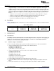
Hardware Resource Mapping www.ti.com Vin-12v Boost V-boost1 + 1A V-boost2 F28027 I-Led1 I-Led2 CPU 32 bit DSP core 60 MHz 3V3 Comms 2 IC SPI UART + 1B ADC 12 bit 4.6 MSPS Vref I-Led8 V-boost1 V-boost6 V-sepic1 V-sepic2 PWM1(HR) 1A / 1B PWM2(HR) 2A / 2B PWM3(HR) 3A / 3B PWM4(HR) 4A / 4B V-boost6 I-Led6 I-Led2 I-Led1 + 3B Figure 8. LED BoosterPack Circuit Diagram 5.2 Jumpers, Connectors, and Switches Table 3 lists the jumpers, connectors, and switches available on the board.
Hardware Resource Mapping www.ti.com J2 and J8 Power Jumpers J1 Power Input J3,J9 and J4,J10 and J11 LaunchPadXL Socket S1 MSP430 Serial Disconnect Switch J6 and J7 Capacitive Touch BoosterPack Headers J5 MSP430 Programming Interface Figure 9.
EVALUATION BOARD/KIT/MODULE (EVM) ADDITIONAL TERMS Texas Instruments (TI) provides the enclosed Evaluation Board/Kit/Module (EVM) under the following conditions: The user assumes all responsibility and liability for proper and safe handling of the goods. Further, the user indemnifies TI from all claims arising from the handling or use of the goods.
FCC Interference Statement for Class B EVM devices This equipment has been tested and found to comply with the limits for a Class B digital device, pursuant to part 15 of the FCC Rules. These limits are designed to provide reasonable protection against harmful interference in a residential installation. This equipment generates, uses and can radiate radio frequency energy and, if not installed and used in accordance with the instructions, may cause harmful interference to radio communications.
【Important Notice for Users of this Product in Japan】 】 This development kit is NOT certified as Confirming to Technical Regulations of Radio Law of Japan If you use this product in Japan, you are required by Radio Law of Japan to follow the instructions below with respect to this product: 1. 2. 3. Use this product in a shielded room or any other test facility as defined in the notification #173 issued by Ministry of Internal Affairs and Communications on March 28, 2006, based on Sub-section 1.
EVALUATION BOARD/KIT/MODULE (EVM) WARNINGS, RESTRICTIONS AND DISCLAIMERS For Feasibility Evaluation Only, in Laboratory/Development Environments. Unless otherwise indicated, this EVM is not a finished electrical equipment and not intended for consumer use.
IMPORTANT NOTICE Texas Instruments Incorporated and its subsidiaries (TI) reserve the right to make corrections, enhancements, improvements and other changes to its semiconductor products and services per JESD46, latest issue, and to discontinue any product or service per JESD48, latest issue. Buyers should obtain the latest relevant information before placing orders and should verify that such information is current and complete.