
User manual


Connector Interface
www.ti.com
8 Connector Interface
The following connectors are used for external interface to the AFE44x0 Pulse Oximeter board.
• DB9
• USB mini connector
8.1 DB9 Pulse Oximeter Connector
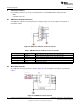
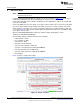
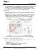
The DB9 pulse oximeter connector pinouts are shown in Figure 42. The description of the pinouts is
provided in Table 6
Figure 42. DB9 Pulse Oximeter Connector Pinouts
Table 6. DB9-Based Pulse Oximeter Connector Pinouts
Pin Number Pin Name Pin Description
2 TX_LED_P Anode of the LED1 (IR LED), cathode of the LED2 (red LED)
3 TX_LED_N Cathode of the LED1 (IR LED), anode of the LED2 (red LED)
5 DET_N Phototransistor anode
7 GND Cable shield
9 DET_P Phototransistor cathode
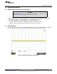
8.2 Mini USB Connector
The USB mini connector pinouts are shown in Figure 43. The description of the pinouts is provided in
Table 7.
Figure 43. USB Mini Connector Pinouts
34
AFE4400 and AFE4490 Development Guide SLAU480C–January 2013–Revised May 2014
Submit Documentation Feedback
Copyright © 2013–2014, Texas Instruments Incorporated