
User manual

www.ti.com
AFE44x0SPO2EVM Hardware
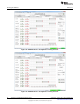
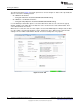
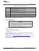
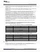
Table 1 contains the Save tab control descriptions.
Table 1. Save Tab Control Descriptions
Button/Control Description
Saves the scope analysis result.
Scope Analysis
The result is saved in the file Device_<record number>_Analysis.xls.
Saves the FFT analysis result.
FFT Analysis
The result is saved in the file Device_<record number>_Analysis.xls.
Saves the histogram analysis result.
Histogram Analysis
The result is saved in the file Device_<record number>_Analysis.xls.
All the current register values are read from the EVM and stored.
Register Settings
The result is saved in the file Device_<record number>_Analysis.xls.
Data – Codes Acquired data sample values are stored to the file Device_ <record number>_Codes.xls.
FFT Data Acquired data sample’s FFT values are stored to the file Device_ <record number>_FFT.xls.
Histogram Data Acquired data sample’s histogram values are stored to the file Device_ <record number>_Histogram.xls.
The Record Number saves files with the provided number in the file name. User notes can also be added
to the file by typing the notes in the User Comments control.
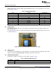
5 AFE44x0SPO2EVM Hardware
CAUTION
Many of the components on the AFE44x0SPO2EVM are susceptible to damage
by electrostatic discharge (ESD). Customers are advised to observe proper
ESD handling precautions when unpacking and handling the EVM, including
the use of a grounded wrist strap, bootstraps, or mats at an approved ESD
workstation. Safety glasses should also be worn.
The key features of the AFE44x0 Analog Front End demonstration board are:
• Based on MSP430F5529
• DB9 pulse oximeter sensor cable support
• Acquire data at up to 3000 Hz in evaluation mode
• SPI Data interface
The AFE44x0SPO2EVM board can be used as a demo board for pulse oximeter and heart rate
applications. The BOM is provided in Section 11. The printed circuit board (PCB) and schematic are
shown in Section 12.1 and Section 12.2, respectively.
MSP430F5529 (U2 – see Section 12.2) is the microcontroller used on the board. For more details of the
MSP430F5529 please visit http://focus.ti.com/docs/prod/folders/print/msp430f5529.html
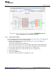
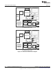
The following sections explain the main hardware components available on the EVM. Figure 34 shows the
functional block diagram for the EVM.
27
SLAU480C–January 2013–Revised May 2014 AFE4400 and AFE4490 Development Guide
Submit Documentation Feedback
Copyright © 2013–2014, Texas Instruments Incorporated