
User manual

www.ti.com
Running the Software
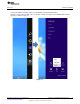
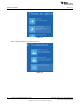
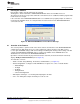
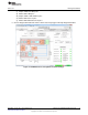
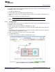
4.1.1.2 Tx Stage Subtab
The Tx Stage subtab under the Device Configuration tab, shown in Figure 24 for AFE4490 and Figure 25
for AFE4400, consists of the settings to:
1. Set LED1 and LED2 currents.
2. Program LED current control DAC through a pull-down menu.
3. Program the transmitter reference voltage through a pull-down menu (available for AFE4490 device
only).
4. Select between H-bridge mode and Push-pull mode.
NOTE: The AFE44x0SPO2EVM does not support Push-pull mode.
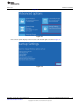
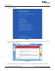
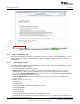
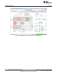
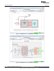
4.1.1.3 Rx Stage Subtab
The Rx Stage subtab under the Device Configuration tab, shown in Figure 26 for AFE4490 and Figure 27
for AFE4400, consists of the settings to:
1. Enable separate gain mode (available for AFE4490 device only).
2. Set feedback resistance and capacitance for the trans-impedance amplifier with separate gain mode
disabled.
3. Set feedback resistance and capacitance for the trans-impedance amplifier with separate gain mode
enabled (available for AFE4490 device only).
4. Enable second-stage and set gain for the second-stage amplifier.
5. Set ambient DAC current.
6. Select filter corner frequency (available for AFE4490 device only).
Figure 24. AFE4490: Device Configuration: Tx Stage
19
SLAU480C–January 2013–Revised May 2014 AFE4400 and AFE4490 Development Guide
Submit Documentation Feedback
Copyright © 2013–2014, Texas Instruments Incorporated