User's Guide SLAU480C – January 2013 – Revised May 2014 AFE4400 and AFE4490 Development Guide This user’s guide describes the characteristics, operation, and use of the AFE44x0SPO2EVM demonstration kit. This demonstration kit is an evaluation module (EVM) for the AFE4400 and AFE4490 family of devices. The family of devices are fully-integrated AFE, ideally suited for pulse oximeter applications. The EVM is intended for prototyping and evaluation.
AFE44x0SPO2EVM Overview 11 12 www.ti.com 10.8 Windows 8 Support for Device GUIs ........................................................................... 10.9 COM Port ........................................................................................................... Bill of Materials ............................................................................................................. PCB Layouts and Schematics ............................................................................
Overview www.ti.com 2 Overview 2.1 Introduction NOTE: From this point on, unless otherwise noted, AFE44x0 refers to AFE4400- and AFE4490based demonstration kits. The EVM is intended for evaluating AFE4400 and AFE4490 devices. The family of devices consist of a low-noise receive channel, the LED transmit section, and diagnostics for sensor and LED fault detection. The AFE44x0 has a highly configurable timing controller, enabling complete control of the device’s timing characteristics.
Software Installation www.ti.com 4. Access to all AFE44x0 registers through an easy-to-use GUI 5. Built-in time domain, histogram, FFT, and related analysis on the PC application 6. USB-based firmware upgrade option 3 Software Installation The latest AFE44x0SPO2EVM PC application software (GUI) is available from the TI website, AFE4400SPO2EVM GUI and AFE4490SPO2EVM GUI. Download the zipped file to a temporary directory on the PC. 3.
Software Installation www.ti.com 3.2 Installing the Software (PC Application) Before installing the software, make sure the AFE44x0SPO2EVM is NOT connected to the PC. If using a machine with Windows 7 or Windows 8 OS, TI recommends having administrator rights to avoid problems during installation. Unzip the installer file, and then find and double click setup.exe to install the software.
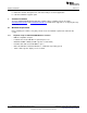
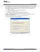
Software Installation www.ti.com Accept the Texas Instruments end-user license agreement (EULA) and click the Next button. Figure 3. PC Application Installation – Screen 2 Accept the National Instruments™ software license agreement and click the Next button. Figure 4.
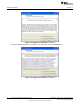
Software Installation www.ti.com Click the Next button to begin the installation. Figure 5. PC Application Installation – Screen 4 The application software is now installed. After the installation is complete, click the Next button to continue with the installation of Python v2.7. Figure 6. PC Application Installation – Screen 5 After the Python v2.7 is installed, click OK. The PC application is now ready to use. Figure 7.
Software Installation 3.3 www.ti.com Installing the USB Drivers The communication interface between the AFE44x0SPO2EVM board and PC is through the USB, using the CDC profile. A one-time installation of the USB driver is required for the communication between the AFE44x0SPO2EVM and PC application. NOTE: For Windows 8, signed driver enforcement may have to be disabled. Section 3.3.1 explains how to do this. Following these steps ensures proper installation of the USB drivers: 1.
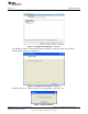
Software Installation www.ti.com 3. Select the Install from a list or specific locations (Advanced) option, and click the Next button. Figure 9. USB Driver Installation – Screen 2 4. As shown in Figure 10, navigate to the directory where the AFE44x0.inf file is located by clicking the Browse button.
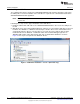
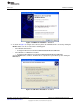
Software Installation www.ti.com 5. Click the Finish button after the driver installation is complete (Figure 11). Figure 11. USB Driver Installation – Screen 4 6. The AFE44x0SPO2-FE EVM is now recognized as Virtual COM Port under the Device Manager as shown in Figure 12. Figure 12. Device Manager Screen The USB driver installation is now complete and the EVM is ready to use.
Software Installation www.ti.com 3.3.1 Windows 8 Installing Unsigned Drivers Perform an advanced startup sequence to let Windows 8 install unsigned drivers. Move the cursor to the top right of the screen, click settings, then power, then HOLD SHIFT and click Restart as shown in Figure 13. Figure 13.
Software Installation www.ti.com After a loading screen, three options appear. Choose Troubleshoot as shown in Figure 14. Figure 14. Choose advanced options as shown in Figure 15. Figure 15.
Software Installation www.ti.com Choose startup Settings as shown in Figure 16. Figure 16. Next a list of options displays. Click Restart at the bottom right as shown in Figure 17. Figure 17.
Software Installation www.ti.com After the computer restarts, the following screen appears (see Figure 18). Press F7 to disable driver signature enforcement. Figure 18. Now, the user can install unsigned drivers. A warning may appear as shown in Figure 19; choose Install this driver software anyway. Figure 19. Restart the computer again to re-enable driver signature enforcement after the installation is complete.
Running the Software www.ti.com 4 Running the Software Run the GUI software from the Start menu by selecting All Programs→Texas Instruments→AFE44x0SPO2EVM GUI. Unless the hardware has been disconnected, observe messages that confirm the connection has been established and the program waits in idle mode for user input.
Running the Software www.ti.com Figure 21. Product Safety Warnings, Restrictions, and Disclaimers 4.1.1 Device Configuration Tab The Device Configuration tab allows configuration of the various registers of the AFE44x0 device. This subtab contains five subtabs: Global Settings, Tx Stage, Rx Stage, Timing Controls, and Low Level Configuration. 4.1.1.
Running the Software www.ti.com (i) Sample LED2 and LED1 pulse (ii) LED2 / LED1 LED pulse (iii) Sample LED2 / LED1 Ambient pulse (iv) LED2 / LED1 Convert pulse (v) LED2 / LED1 Ambient Convert pulse 5. Click on Diagnostic Enable and view the Alarm status flags triggered through Diagnostic Enable. Figure 22.
Running the Software www.ti.com Figure 23.
Running the Software www.ti.com 4.1.1.2 Tx Stage Subtab The Tx Stage subtab under the Device Configuration tab, shown in Figure 24 for AFE4490 and Figure 25 for AFE4400, consists of the settings to: 1. Set LED1 and LED2 currents. 2. Program LED current control DAC through a pull-down menu. 3. Program the transmitter reference voltage through a pull-down menu (available for AFE4490 device only). 4. Select between H-bridge mode and Push-pull mode. NOTE: The AFE44x0SPO2EVM does not support Push-pull mode.
Running the Software www.ti.com Figure 25. AFE4400: Device Configuration: Tx Stage Figure 26.
Running the Software www.ti.com Figure 27. AFE4400: Device Configuration: Rx Stage 4.1.1.4 Timing Controls Subtab The Timing Controls subtab under the Device Configuration tab, shown in Figure 28 for AFE4490 and Figure 29 for AFE4400, consists of the following settings: 1.
Running the Software www.ti.com Figure 28. AFE4490: Device Configuration: Timing Controls Figure 29.
Running the Software www.ti.com 4.1.1.5 Low Level Configuration Subtab The Low Level Configuration subtab under the Device Configuration tab is used to directly configure the various registers of the AFE44x0 devices. Refer to the AFE44x0 data sheet (SBAS601, SBAS602) for the register details of the chip. Figure 30 shows the low-level configuration registers of the AFE44x0 devices.
Running the Software • • • www.ti.com Set Analysis Type to All Domain or Time Domain only Auto save after capture selector Acquire the data by clicking the Capture button – When the user selects the auto save after capture selector under 'ADC Capture & Analysis' tab, the GUI uses the settings selected under 'Analysis to Save,' 'Channels to Save,' 'Data to Save,' and 'Save File Settings'. The user will be notified with a 'Results saved successfully!' after every capture.
Running the Software www.ti.com 4. No. of samples = 30 Data rate (sps) = 500 Show data for the last 1 secs Then display Error message “Insufficient # of samples for FFT calculation” since # of samples for FFT which is power of 2 = 16 ≤ min ( (500 x 1) , 30 ) 5. No. of samples = 32 Data rate (sps) = 500 Show data for the last 2 secs # of samples for FFT which is power of 2 = 32 ≤ min ( (500 x 2) , 32 ) Since (# of samples for FFT calc. == No.
Running the Software 4.1.3 www.ti.com Save Tab The Save tab shown in Figure 33 provides provisions to save the analysis or data to a file. By default, the data are saved to the following location: • • On a Windows XP machine – C:\Program Files\Texas Instruments\AFE44x0SPO2EVM GUI\Log On a Windows 7 or Windows 8 machine – C:\Program Files(x86)\Texas Instruments\AFE44x0SPO2EVM GUI\Log Use the Directory to Save Files option to select the folder where data are to be saved.
AFE44x0SPO2EVM Hardware www.ti.com Table 1 contains the Save tab control descriptions. Table 1. Save Tab Control Descriptions Button/Control Description Scope Analysis Saves the scope analysis result. The result is saved in the file Device__Analysis.xls. FFT Analysis Saves the FFT analysis result. The result is saved in the file Device__Analysis.xls. Histogram Analysis Saves the histogram analysis result. The result is saved in the file Device__Analysis.
AFE44x0SPO2EVM Hardware www.ti.com 6pin eZ430 RF header UART SD CARD AFE4490 SPI MSP430F5529 SPI 2Mb FRAM 2Mb FRAM Memory Block MSP Reset Switch DB9 Connector Accelerometer MSP JTAG Header USB Reset Switch I2C AFE4490 Evaluation Module AFE RX 3V LDO AFE TX 5V LDO MSP430 3V LDO Batt FuelGauge Boost Converter Battery Mgmt Mini USB Battery Header Power Management Block a.
AFE44x0SPO2EVM Hardware www.ti.com 5.1 Power Supply AFE4490 can operate from 2.0- to 3.6-V Rx analog supply (RX_ANA_SUP), 2.0- to 3.6-V Rx digital supply (RX_DIG_SUP), 3.0- to 5.25-V Tx Control supply (TX_CTRL_SUP) and LED driver supply (LED_DRV_SUP). AFE4400 can operate from 2.0- to 3.6-V Rx analog supply (RX_ANA_SUP), 2.0- to 3.6-V Rx digital supply (RX_DIG_SUP), 3.0- to 3.6-V Tx Control supply (TX_CTRL_SUP) and LED driver supply (LED_DRV_SUP).
AFE44x0SPO2EVM Hardware 5.3 www.ti.com Accessing AFE44x0 Digital Signals AFE44x0 SPI interface and other digital signals with MSP430 can be accessed through the series resistor jumpers given in Table 4. Table 4. AFE44x0 Digital Signals 5.4 S. No.
AFE44x0SPO2EVM Hardware www.ti.com 5.7 Visual Indication The blue LED (LED3) indicates the USB power connection. The blue LED (LED1) indicates that the microcontroller is busy servicing the requests from the PC application. 6 USB-Based Firmware Upgrade NOTE: AFE44x0SPO2EVM GUI v2.0 works with FW rev 1.3. Follow the steps outlined in this section to upgrade the firmware to rev 1.3.
USB-Based Firmware Upgrade www.ti.com – On a Windows XP machine: • C:\Program Files\Texas Instruments\AFE44x0SPO2EVM GUI\Firmware Updater – On a Windows 7 or Windows 8 machine: • C:\Program Files(x86)\Texas Instruments\AFE44x0SPO2EVM GUI\Firmware Updater Figure 38. PC Application Firmware Upgrade – 3 • Once the device is programmed successfully, as shown in Figure 39, the device resets and reloads with the new firmware.
GUI Update www.ti.com 7 GUI Update The user can check for the latest version of the GUI by selecting 'Check for New GUI Version' from the menu options on the PC application as shown in Figure 40. Figure 40. Check for New GUI Version When a newer version of the GUI is available, a pop-up message will appear letting the user to download the update now or at a later time.
Connector Interface 8 www.ti.com Connector Interface The following connectors are used for external interface to the AFE44x0 Pulse Oximeter board. • DB9 • USB mini connector 8.1 DB9 Pulse Oximeter Connector The DB9 pulse oximeter connector pinouts are shown in Figure 42. The description of the pinouts is provided in Table 6 Figure 42. DB9 Pulse Oximeter Connector Pinouts Table 6. DB9-Based Pulse Oximeter Connector Pinouts 8.
Connector Interface www.ti.com Table 7.
Quick Start Guide 9 www.ti.com Quick Start Guide NOTE: For all the measurements shown in the following, ProSim Fluke SPOT Light SpO2 Functional tester was used. • • • • • • • Install the AFE44x0SPO2EVM GUI PC Software (Check the TI website at www.ti.
AFE44x0SPO2EVM FAQs www.ti.com 10 AFE44x0SPO2EVM FAQs 10.1 EVM Communicating With the PC Application CAUTION AFE44x0SPO2EVM GUI v.2.0 works with FW revision 1.3. Follow the steps outlined in Section 6 to upgrade the firmware to revision 1.3. A quick and simple check to verify serial register write operation is to put the AFE44x0 in power-down mode. Follow the sequence to check if the GUI is communicating with the EVM.
AFE44x0SPO2EVM FAQs www.ti.com 10.3 Check TXP and TXM Waveforms TXP and TXM waveforms are observed at TX_P (TP23) and TX_N (TP17). Figure 46 shows TXP and TXM waveforms without connecting the pulse oximeter cable. Figure 47 shows TXP and TXM waveforms after connecting the pulse oximeter cable. Figure 46. TXP and TXM Without Pulse Oximeter Cable Figure 47.
AFE44x0SPO2EVM FAQs www.ti.com 10.4 Using an External ADC (Bypass ADC Mode) (Available Only for AFE4490 Device) AFE4490 has a mode where the front-end analog output voltage becomes available on two pins (RX_OUTP, RX_OUTN), around a common-mode voltage of about 0.9 V. In this mode, the internal ADC of AFE4490 is disabled, one of the internal ADC_RESET clocks is brought out on the PD_ALM pin (PD_ALM is monitored at series jumper resistor R37).
AFE44x0SPO2EVM FAQs www.ti.com 10.7 Optimum Viewing Experience on Windows 7 OS • Change the size of text to Smaller – 100% for optimum viewing experience on Windows 7 operating system as shown in Figure 49. Figure 49. Setting Font Size on Windows 7 Operating System 10.8 Windows 8 Support for Device GUIs At GUI Start up, sometimes the GUI might show a broken arrow as seen in Figure 50. One of the reasons for this issue may be due to a missing update of .NET FRAMEWORK 3.5 (includes .NET 2.0 and .NET 3.
AFE44x0SPO2EVM FAQs www.ti.com Points to Remember: • There is no download for the .NET Framework 3.5 for Windows 8 or Windows 8.1. The user must enable the .NET Framework 3.5 in Control Panel by following the instructions provided in this article. • Use the .NET Framework 3.5 for apps built for versions 2.0 and 3.0 as well as 3.5. • Installing a Windows language pack before installing the .NET Framework 3.5 will cause the .NET Framework 3.5 installation to fail. Install the .NET Framework 3.
AFE44x0SPO2EVM FAQs www.ti.com Figure 52. Select Download and Install this feature. Figure 53.
AFE44x0SPO2EVM FAQs www.ti.com Select Download Files from Windows Update. Figure 54. Figure 55.
AFE44x0SPO2EVM FAQs www.ti.com Figure 56. 10.8.2 Method 2 (Enabling .NET Framework 3.5 on Windows 8 in Offline Mode) This is basically using Windows 8 CD to enable/install .NET FRAMEWORK 3.5 in the PC. This method does not require an internet connection. Step 1: Insert Windows 8 DVD or mount ISO image. The source of this feature can be found in folder E:\sources\sxs. (In this case E: is the user’s drive letter on which the user has loaded Windows 8 Media.) Figure 57.
AFE44x0SPO2EVM FAQs www.ti.com Step 2: Open Command prompt as administrator. Figure 58. Figure 59.
AFE44x0SPO2EVM FAQs www.ti.com Step 3: Run the following command Dism.exe /online /enable-feature /featurename:NetFX3 /All /Source:E:\sources\sxs /LimitAccess, and hit Enter. Make sure to choose the appropriate drive letter (in this case it is E:\). Figure 60. Method 2 source: http://support.microsoft.com/kb/2785188 Table 8. Troubleshoot and Links Description Link Installing the .NET Framework 3.5 on Windows 8 or 8.1 http://msdn.microsoft.com/library/hh506443(v=VS.110).aspx Enable .NET Framework 3.
Bill of Materials www.ti.com 11 Bill of Materials The following pages show the bill of materials (landscaped for readability). Table 9. AFE44x0SPO2EVM Bill of Materials AFE4400EVM Qty AFE4490EVM Qty REF DES Value or Function Description MFG MFG Part# Comments 1 1 NA 0.062"-FR4-RoHS Printed Circuit Board TI AFE44x0SPO2EVM REV.A 12 12 C1, C3, C4, C8, C9, C10, C14, C16, C20, C22, C26, C30, C31, C33, C34, C37, C38, C43, C49, C50, C53, C57, C66 0.
Bill of Materials www.ti.com Table 9. AFE44x0SPO2EVM Bill of Materials (continued) AFE4400EVM Qty AFE4490EVM Qty 1 2 48 REF DES Value or Function Description MFG MFG Part# 1 R96 1.
Bill of Materials www.ti.com Table 9.
PCB Layouts and Schematics 12 www.ti.com PCB Layouts and Schematics 12.1 AFE44x0SPO2EVM PCB Layouts Figure 61 through Figure 68 show the EVM PCB layouts (landscaped for readability). Figure 61.
PCB Layouts and Schematics www.ti.com Figure 62. AFE44x0SPO2EVM Top Solder Figure 63.
PCB Layouts and Schematics www.ti.com Figure 64. AFE44x0SPO2EVM Bottom Layer Figure 65.
PCB Layouts and Schematics www.ti.com Figure 66. AFE44x0SPO2EVM Bottom Overlay Figure 67.
PCB Layouts and Schematics www.ti.com Figure 68.
PCB Layouts and Schematics www.ti.com 12.2 AFE44x0SPO2EVM Schematics Figure 69 through Figure 72 show the EVM schematics (landscaped for readability). AFE44x0 C6 Y1 1 C7 2 8 MHz 18 pF 0Ω 0Ω 18 pF R17 R16 The following signals need to be considered as two sets of differential pairs and routed as adjacent signals within each pair. 1. TXM and TXP 2. INM and INP R15 0 Ω XIN_MSP DNI RX_DIG_SUP R20 R22 RX_ANA_SUP TP11 130 Ω 130 Ω INM and INP must be guarded with VCM_SHIELD signal.
PCB Layouts and Schematics www.ti.com MSP_DVCC J3 N/C JTAG_TDI MSP_DVCC JTAG_TMS G G N/C Y3 24 MHz JTAG_TCK SBWTCLK C18 C17 3 1 1 2 3 4 5 6 7 8 9 10 4 2 JTAG_TDO SBWTDIO VUSB 10 pF 10 pF TC2050-IDC-FP R83 R82 0Ω 47 kΩ TP19 TP27 TP29 TP15 TP16 TEST TDO SBWTCLK JTAG_TDO JTAG_TDI JTAG_TMS JTAG_TCK TMS TCK TP26 PUR VBUS VBUS VUSB 2 C43 0.1 µF 80 79 78 77 76 75 74 73 72 71 70 69 68 67 66 65 64 63 62 61 2 LED1 Blue SW1 LED2 R4 R3 MSP_AVCC C38 0.
PCB Layouts and Schematics www.ti.com L6 LED_DRV_SUP 1 2 LPS3010-103MLB 0Ω R76 Jumper C65 10 µF L4 1 L5 AFE_5VTX 2 REG_VO R68 0Ω U8 VDD_BAT R71 0Ω Jumper U9 R66 0Ω Jumper C28 10 µF VBT_IN C31 0.1 µF R73 0Ω GND VIN CP2 CP1 EN VO SW OUT FB SS EPAD 10 9 8 7 6 11 AFE_VTX 4 8 R72 261 kΩ SW_LP VDD_BAT REG_FB REG_SS R75 200 kΩ LED3 Blue C63 10 µF C32 10 µF 2 7 9 R81 4.7 kΩ IN OUT SD ADJ NC NC DAP BYP GND 5 C36 R77 1000 pF 4.02 kΩ C29 10 µF C27 R79 0.01 µF 1.
PCB Layouts and Schematics www.ti.com Battery Fuel Gauge Serial FRAM TP41 MSP_DVCC J5 PACK_P TP45 U10 R80 1 kΩ TP40 TP39 1 RBI PGM C33 0.1 µF GPIO 2 3 C34 0.1 µF SCL SCL R109 100 Ω R108 VCC VSS SRP 4 SCL 100 Ω 5 VSS1 SDA R117 100 Ω SDA MEM0_HOLD MEM_SCLK MEM_SIMO C4 0.1 µF U5 1 2 3 4 MEM_CS1 MEM_SOMI MEM1_W TP44 6 C37 8 7 6 5 MSP_DVCC C66 BAT VCC /HOLD C D R114 .02E R118 1 kΩ 7 /S Q /W VSS FM25V20-GTR R70 1 kΩ 0.
Revision C History www.ti.com Revision C History Changes from B Revision (May 2014) to C Revision ...................................................................................................... Page • • Replaced Figure 69 through Figure 72 with updated schematics ................................................................. 55 Removed AFE44x0SPO2EVM Blocks schematic ...................................................................................
ADDITIONAL TERMS AND CONDITIONS, WARNINGS, RESTRICTIONS, AND DISCLAIMERS FOR EVALUATION MODULES Texas Instruments Incorporated (TI) markets, sells, and loans all evaluation boards, kits, and/or modules (EVMs) pursuant to, and user expressly acknowledges, represents, and agrees, and takes sole responsibility and risk with respect to, the following: 1. User agrees and acknowledges that EVMs are intended to be handled and used for feasibility evaluation only in laboratory and/or development environments.
RADIO FREQUENCY REGULATORY COMPLIANCE INFORMATION FOR EVALUATION MODULES Texas Instruments Incorporated (TI) evaluation boards, kits, and/or modules (EVMs) and/or accompanying hardware that is marketed, sold, or loaned to users may or may not be subject to radio frequency regulations in specific countries. General Statement for EVMs Not Including a Radio For EVMs not including a radio and not subject to the U.S.
Canada Industry Canada Compliance (French) Cet appareil numérique de la classe A ou B est conforme à la norme NMB-003 du Canada Les changements ou les modifications pas expressément approuvés par la partie responsable de la conformité ont pu vider l’autorité de l'utilisateur pour actionner l'équipement. Concernant les EVMs avec appareils radio Le présent appareil est conforme aux CNR d'Industrie Canada applicables aux appareils radio exempts de licence.
IMPORTANT NOTICE Texas Instruments Incorporated and its subsidiaries (TI) reserve the right to make corrections, enhancements, improvements and other changes to its semiconductor products and services per JESD46, latest issue, and to discontinue any product or service per JESD48, latest issue. Buyers should obtain the latest relevant information before placing orders and should verify that such information is current and complete.