
Datasheet


ADS5421
12
SBAS237E
www.ti.com
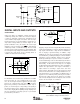
Center Frequency (MHz)
3rd-Order Spurious (dBc)
0
–60
–65
–70
–75
–80
–85
5 101520253035404550
4V
PP
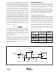
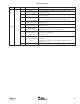
FIGURE 7. Measured 2-Tone, 3rd-Order Distortion for a
Differential ADC Driver.
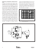
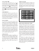
FIGURE 6. High Dynamic Range Interface Circuit with the OPA847 Set for a Gain of +8.5V/V.
ADS5421
47pF
IN
IN
CM
+5V
V
CM
1.7pF
OPA847
OPA847
850Ω
50Ω Source
20Ω
850Ω
100Ω
20Ω
100Ω
39pF
1.7pF
39pF
1:2
T
1
–5V
+5V
–5V
+5V
0.1µF
V
CM
V
CM
< 6dB
Noise
Figure
AC-COUPLED, DIFFERENTIAL INTERFACE WITH
GAIN
The interface circuit example presented in Figure 6 employs
two OPA687s, (decompensated voltage-feedback op amps),
optimized for gains of 12V/V or higher. Implementing a new
compensation technique allows the OPA847s to operate with
a reduced signal gain of 8.5V/V, while maintaining the high
loop gain and the associated excellent distortion perfor-
mance offered by the decompensated architecture. For a
detailed discussion on this circuit and the compensation
scheme, refer to the OPA847 data sheet (SBOS251) located
at www.ti.com. Input transformer, T1, converts the single-
ended input signal to a differential signal required at the
inverting inputs of the amplifier, which are tuned to provide a
50Ω impedance match to an assumed 50Ω source. To
achieve the 50Ω input match at the primary of the 1:2
transformer, the secondary must see a 200Ω load imped-
ance. Both amplifiers are configured for the inverting mode
resulting in close gain and phase matching of the differential
signal. This technique, along with a highly symmetrical lay-
out, is instrumental in achieving a substantial reduction of the
2nd-harmonic, while retaining excellent 3rd-order perfor-
mance. A common-mode voltage, V
CM
, is applied to the
noninverting inputs of the OPA847. Additional series 20Ω
resistors isolate the output of the op amps from the capaci-
tive load presented by the 40pF capacitors and the input
capacitance of the ADS5421. This 20Ω/47pF combination
sets a pole at approximately 85MHz and rolls off some of the
wideband noise resulting in a reduction of the noise floor.
For the measured 2-tone, 3rd-order distortion for the ampli-
fier portion of the circuit of Figure 6, see Figure 7. The curve
is for a total 2-tone envelope of 4V
PP
, requiring two tones,
each 2V
PP
across the OPA847 outputs. The basic measure-
ment dynamic range for the two close-in spurious tones is
approximately 85dBc. The 4V
PP
test does not show measur-
able 3rd-order spurious until 25MHz.