
Datasheet


1.2
1.0
0.8
0.6
0.4
0.2
0
-0.2
0 10 20 30 40
Time(ConversionCycles)
StepResponse
50
20
0
-20
-40
-60
-80
-100
-120
-140
0 1 2 3 54 6 7 8 9
Frequency(MHz)
Magnitude(dB)
10
f =
CLK
20MHz
SYNC
ADS1601
1
CLK
FSO
DOUT
FSO
1
DOUT
1
SYNC
CLK
SYNC
ADS1601
2
CLK
FSO
DOUT
CLK
SYNC
FSO
1
FSO
2
t
STL
FSO
2
DOUT
2
ADS1601
www.ti.com
SBAS322D –DECEMBER 2004–REVISED OCTOBER 2011
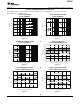
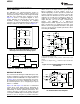
DATA RETRIEVAL STEP RESPONSE
Data retrieval is controlled through a simple serial Figure 44 plots the normalized step response for an
interface. The interface operates in a master fashion input applied at t = 0. The x-axis units of time are
by outputting both a frame sync indicator (FSO) and a conversions cycles. It takes 51 cycles to fully settle;
serial clock (SCLK). Complementary outputs are for f
CLK
= 20MHz, this corresponds to 40.8μs.
provided for the frame sync output (FSO), serial clock
(SCLK), and data output (DOUT). When not needed,
leave the complementary outputs unconnected.
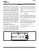
INITIALIZING THE ADS1601
After the power supplies have stabilized, you must
initialize the ADS1601 by issuing a SYNC pulse as
shown in Figure 1. This operation needs only to be
done once after power-up and does not need to be
performed when exiting the Power-Down mode. Note
that the ADS1601 silicon was revised in June 2006.
The digital interface timing specifications were
modified slightly from the previous revision. This data
sheet reflects behavior of the latest revision. Contact
the factory for more information on the previous
revision.
Figure 44. Step Response
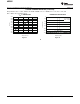
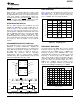
SYNCHRONIZING MULTIPLE ADS1601s
The SYNC input can be used to synchronize multiple
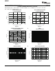
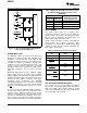
FREQUENCY RESPONSE
ADS1601s to provide simultaneous sampling. All
devices to be synchronized must use a common CLK
The linear phase FIR digital filter sets the overall
input. With the CLK inputs running, pulse SYNC on
frequency response. Figure 45 shows the frequency
the falling edge of CLK, as shown in Figure 43.
response from dc to 10MHz for f
CLK
= 20MHz. The
Afterwards, the converters will be converting
frequency response of the ADS1601 filter scales
synchronously with the FSO outputs updating
directly with CLK frequency. For example, if the CLK
simultaneously. After synchronization, FSO is held
frequency is decreased by half (to 10MHz), the
low until the digital filter has fully settled.
values on the X-axis in Figure 45 would need to be
scaled by half, with the span becoming dc to 5MHz.
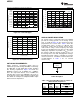
Figure 46 shows the passband ripple from dc to
600kHz (f
CLK
= 20MHz). Figure 47 shows a closer
view of the passband transition by plotting the
response from 400kHz to 650kHz (f
CLK
= 20MHz).
Figure 45. Frequency Response
Figure 43. Synchronizing Multiple Converters
Copyright © 2004–2011, Texas Instruments Incorporated 19