
Datasheet


"###$
SBAS282D − JUNE 2003 − REVISED MARCH 2004
www.ti.com
13
APPLICATIONS INFORMATION
The sections that follow give example circuits and tips for
using the ADS1112 in various situations.
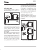
BASIC CONNECTIONS
For many applications, connecting the ADS1112 is
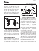
extremely simple. A basic connection diagram for the
ADS1112 is shown in Figure 4.
Figure 4. Typical Connections of the ADS1112
The fully differential voltage input of the ADS1112 is ideal
for connection to differential sources with moderately low
source impedance, such as bridge sensors and
thermistors. Although the ADS1112 can read bipolar
differential signals, it cannot accept negative voltages on
either input. It may be helpful to think of the ADS1112
positive voltage input as non−inverting, and of the negative
input as inverting.
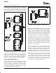
When the ADS1112 is converting, it draws current in short
spikes. The 0.1µF bypass capacitor supplies the
momentary bursts of extra current needed from the supply.
The ADS1112 interfaces directly to standard mode, fast
mode, and high-speed mode I
2
C controllers. Any
microcontroller’s I
2
C peripheral, including master-only
and non-multiple-master I
2
C peripherals, will work with the
ADS1112. The ADS1112 does not perform
clock-stretching (that is, it never pulls the clock line low),
so it is not necessary to provide for this unless
clock-stretching devices are on the same I
2
C bus.
Pull-up resistors are required on both the SDA and SCL
lines because I
2
C bus drivers are open-drain. The size of
these resistors depends on the bus operating speed and
capacitance of the bus lines. Higher-value resistors
consume less power, but increase the transition times on
the bus, limiting the bus speed. Lower-value resistors
allow higher speed at the expense of higher power
consumption. Long bus lines have higher capacitance and
require smaller pull-up resistors to compensate. The
resistors should not be too small; if they are, the bus drivers
may not be able to pull the bus lines low.
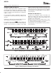
CONNECTING MULTIPLE DEVICES
Connecting multiple ADS1112s to a single bus is trivial.
Using pins A1 and A0, the ADS1112 can be set to one of
eight different I
2
C addresses. An example showing three
ADS1112s is given in Figure 5. Up to eight ADS1112s
(using different states of pins A1 and A0) can be connected
to a single bus.
Figure 5. Connecting Multiple ADS1112s