
Datasheet


Table Of Contents
- Features
- Applications
- Key Specifications
- Description
- Absolute Maximum Ratings
- Operating Ratings
- Package Thermal Resistance
- Converter Characteristics
- DC Electrical Characteristics
- AC Electrical Characteristics
- TRI-STATE Test Circuits and Waveforms
- Typical Performance Characteristics
- Functional Description
- Revision History
ADC10662, ADC10664
www.ti.com
SNAS076E –JUNE 1999–REVISED MARCH 2013
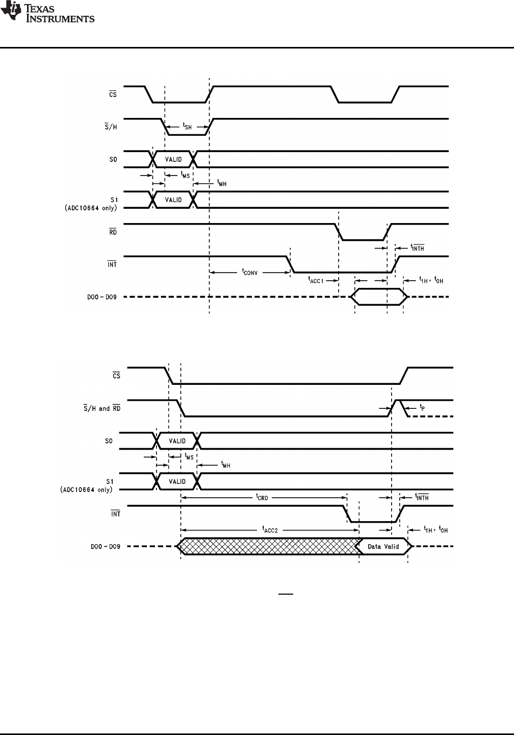
Timing Diagrams
The conversion time (t
CONV
) is set by the internal timer.
Figure 3. Mode 1
The conversion time (t
CRD
) includes the
sampling time and is determined by the internal timer.
Figure 4. Mode 2 (RD Mode)
Copyright © 1999–2013, Texas Instruments Incorporated Submit Documentation Feedback 7
Product Folder Links: ADC10662 ADC10664