
Datasheet


ADC0844, ADC0848
www.ti.com
SNAS523D –JUNE 1999–REVISED MARCH 2013
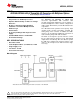
Functional Description
The ADC0844 and ADC0848 contain a 4-channel and 8-channel analog input multiplexer (MUX) respectively.
Each MUX can be configured into one of three modes of operation differential, pseudo-differential, and single
ended. These modes are discussed in Applications Information. The specific mode is selected by loading the
MUX address latch with the proper address (see Table 1 and Table 2). Inputs to the MUX address latch (MA0-
MA4) are common with data bus lines (DB0-DB4) and are enabled when the RD line is high. A conversion is
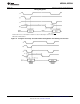
initiated via the CS and WR lines. If the data from a previous conversion is not read, the INTR line will be low.
The falling edge of WR will reset the INTR line high and ready the A/D for a conversion cycle. The rising edge of
WR, with RD high, strobes the data on the MA0/DB0-MA4/DB4 inputs into the MUX address latch to select a
new input configuration and start a conversion. If the RD line is held low during the entire low period of WR the
previous MUX configuration is retained, and the data of the previous conversion is the output on lines DB0-DB7.
After the conversion cycle (t
C
≤ 40 μs), which is set by the internal clock frequency, the digital data is transferred
to the output latch and the INTR is asserted low. Taking CS and RD low resets INTR output high and outputs the
conversion result on the data lines (DB0-DB7).
APPLICATIONS INFORMATION
MULTIPLEXER CONFIGURATION
The design of these converters utilizes a sampled-data comparator structure which allows a differential analog
input to be converted by a successive approximation routine.
The actual voltage converted is always the difference between an assigned “+” input terminal and a “−” input
terminal. The polarity of each input terminal of the pair being converted indicates which line the converter expects
to be the most positive. If the assigned “+” input is less than the “−” input the converter responds with an all zeros
output code.
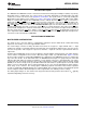
A unique input multiplexing scheme has been utilized to provide multiple analog channels. The input channels
can be software configured into three modes: differential, single ended, or pseudo-differential. Figure 12 shows
the three modes using the 4-channel MUX ADC0844. The eight inputs of the ADC0848 can also be configured in
any of the three modes. In the differential mode, the ADC0844 channel inputs are grouped in pairs, CH1 with
CH2 and CH3 with CH4. The polarity assignment of each channel in the pair is interchangeable. The single-
ended mode has CH1–CH4 assigned as the positive input with the negative input being the analog ground
(AGND) of the device. Finally, in the pseudo-differential mode CH1–CH3 are positive inputs referenced to CH4
which is now a pseudo-ground. This pseudo-ground input can be set to any potential within the input common-
mode range of the converter. The analog signal conditioning required in transducer-based data acquisition
systems is significantly simplified with this type of input flexibility. One converter package can now handle ground
referenced inputs and true differential inputs as well as signals with some arbitrary reference voltage.
The analog input voltages for each channel can range from 50 mV below ground to 50 mV above V
CC
(typically
5V) without degrading conversion accuracy.
Copyright © 1999–2013, Texas Instruments Incorporated Submit Documentation Feedback 9
Product Folder Links: ADC0844 ADC0848