
Installation Guide
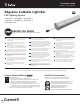


Tetra
®
EdgeLine Cuttable Light Bar Installation Guide
7
Attaching Light Bar Sections
Planning rst:
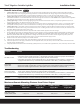
For multiple bar installations, see the “Maximum Light Bars in Series Connection” specication in the Maximum
Loading chart below. Do not exceed the maximum series length per Leader Cable.
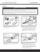
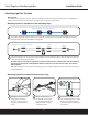
Mounting Option A (standard or slim mounting clips)
Press each light bar into its mounting clips and slide it into the adjacent light so that the alignment features
in the end caps mate with each other.
To avoid stress and damage to light bar the entire mounting surface should be at and the mounting
clips be properly aligned. If the alignment features in the end caps do not mate easily, do not force
them together.
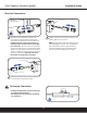
TIP: Align light bar on one side of the mounting clips; then rotate the light bar until it snaps into other side of
the mounting clips.
Secure two mounting clips per light bar to a rigid at mounting surface using two #10 (M5) self-tapping
athead screws along the intended run of light bar.
Align using chalk line, laser projector or similar
Rotate and Push
Alignment features male to female
SNAP!
SNAP!
Male connector towards electrical supply
1
2
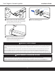
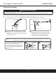
Mounting Option B (standard mounting clips only)
Mount the light bar to
the desired surface using
two #10 (M5) self-tapping
athead screws in each
mounting bracket.
Mount the next light bar down
the row following steps 1 and 2,
being sure to align the light
using the alignment features on
the end cap.
Assemble the light bar by
pressing two mounting
clips onto the light bar. A
snapping noise should be
heard.
1 2 3
SNAP!