
Installation Guide
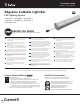


Tetra
®
EdgeLine Cuttable Light Bar Installation Guide
10
Troubleshooting
Symptom Solution
All LEDs are OFF
• Check AC input connection and/or check circuit breaker.
• Check wire connection(s) at the Tetra
®
LED System and power supply for improper termination(s)
or short circuits. Properly terminate or replace the wire connection(s).
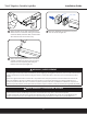
• Check that connections are the red striped wire (+) of the LED strip to the red wire (+) of the power
supply and the white wire (-) of the LED strip to the black or blue wire (-) of the power supply.
Some LEDs
appear dim
• Ensure the overall length of the Tetra
®
LED System does not exceed the maximum load.
• Ensure the length of supply wire is equal to or below the recommended remote mounting distance.
• Ensure the overall length of the Tetra
®
LED System does not exceed the maximum load.
Some of the LEDs
are not illuminated
• Check wire connection(s) at the Tetra
®
LED System and power supply for improper termination(s) or
short circuits. Properly terminate or replace the wire connection(s).
• Check that connections are the red striped wire (+) of the LED strip to the red wire (+) of the power
supply and the white wire (-) of the LED strip to the black or blue wire (-) of the power supply.
Shadows • Adjust LED layout to ensure uniformity of illumination on the face of the letter.
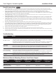
Power Supply
Wattage
18 AWG/0.82 mm
2
Supply Wire
16 AWG/1.31 mm
2
Supply Wire
14 AWG/2.08 mm
2
Supply Wire
12 AWG/3.31 mm
2
Supply Wire
25W 66 ft./20.1 m - - -
60W, 80W, 100W,
180W, 200W, 300W
5 ft./1.5 m 8 ft./2.4 m 14 ft./4.3 m 22 ft./6.7 m
Maximum Remote Mounting Distance from Driver Output
1. (Existing Signs Only) Prior to installation, survey the site for information regarding power and accessibility inside and outside the building.
Ensure that the branch circuit supplying the existing transformer or ballast will be within the voltage ratings of the new LED power supply, and
have a current rating not exceeding 20A, or that permitted by applicable local, state, or country electrical codes (whichever is less).
2. (Existing Signs Only) Remove the existing lighting equipment to be replaced, such as neon tubing or uorescent tubes; and associated
transformers and ballasts. Care should be taken not to break the existing neon or uorescent tubes. NOTE: Follow all federal and local regulations
when disposing of neon tubing, uorescent tubes, transformers and ballasts.
3. (Existing Signs Only) If removal of the existing lighting equipment eliminates the disconnect switch, as required by applicable local, state, or
country electrical codes; a new disconnect switch must be installed.
4. (Existing Signs Only) Repair and seal any unused openings in the electrical enclosure. Openings greater than 12.7mm (1/2-in) diameter require
a metal patch secured by screws or rivets and caulked with non-hardening caulk. Smaller openings may be sealed with non-hardening caulk.
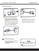
5. (Existing Signs Only) A clean and dry mounting surface ensures optimum adhesion if the self-adhesive method of mounting is chosen. Follow
the manufacturer’s directions when using a non-oil based solvent, such as rubbing alcohol to clean the surface area where you intend to mount
the module. Before installing, ensure the surface is dry.
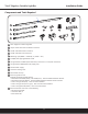
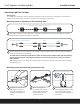
6. Using the layout guidelines above, determine required number of LED modules required to illuminate the sign.
7. For UL retrot sign conversions, the following 24VDC Class 2 Power Supplies must be used: GEPS24-25U-NA, GEPS24D-60U-GLX, GELP24-60U-
GL, GEPS24D-80U, GEPS24-100U-GLX, GEPS24D-100U-NA, USVI-100024FE, USVI-100024FBA, GEPS24-100U-GLX2, GEPS24-100U-TT, GEPS24-
200U-GLX2, GEPS24-300U-GLX2. Using the Maximum Loading chart below, determine the number of Power Supplies required to power the
number of LED modules required to illuminate the sign, so as not to overload the Power Supply chosen.
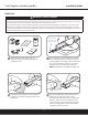
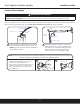
8. Follow the instructions above to properly mount the LED modules.
9. Connect the DC output of the power supply to the LED modules using the Electrical Connections instructions above.
10. Connect the power unit to the supply in accordance with the applicable local, state, and country electrical codes, and the instructions found in
the power supply installation guide.
11. If required, the disconnect switch shall be installed by qualied personnel, in accordance with applicable local, state, and country electrical codes.
Retrot Instructions
FOR UL ONLY