
User Manual

7 Carrying out a measurement
12
7.2. Voltage measurement
✓ Instrument is switched on.
When measuring AC voltage, the frequency is measured at the
same time and shown in the relevant row on the LC display. .
Automatic measuring mode
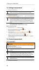
1. Connect test leads: black test lead to the COM jack; red test lead to the
V/Ω/diode/capacitance jack.
The instrument features a built-in zero crossing detector. When the
measured signal (voltage or current) indicates zero crossings, the
instrument automatically switches to AC measuring mode. If no
continuity is indicated, the instrument switches to DC measuring
mode.
2. Connect test lead to the test object.
- The measured value is shown on the LC display.
Manual measuring mode
✓ Instrument is in AUTO V measuring mode.
1. Exit automatic measuring mode: press [] <1 s.
- The instrument is in V AC mode.
2. Switch between V AC, V DC, mV AC and mV DC: press [] <1 s.
- The measured value is shown on the LC display.
3. Switch to automatic measuring mode: press [] >1 s.
- The instrument is in automatic measuring mode when AUTO appears
on the LC display.
7.3. Current measurement
7.3.1. testo 760-1
WARNING
Serious risk of injury to the user and/or destruction of the instrument
while measuring current.
> Measuring circuit must be de-energized.
If fuses blow, please eliminate the cause of this before changing
the fuse.
The measuring instrument may only be used in 16A fused
electrical circuits up to a nominal voltage of 600V. The nominal
cross-section of the connection cable must be taken into account
in order to ensure safe connection (e.g. via crocodile clips).
Strong interferences in the vicinity result in an unstable display and
measurement errors.
✓ Instrument is switched on.