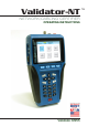
Validator-NT NETWORK/CABLING CERTIFIER OPERATING INSTRUCTIONS Validator NT955 TM
TM VALIDATOR-NT CONTEXT SENSITIVE KEYPAD Test Results 2004 Oct11 10:53:01 50% Untitled1.job Cable001 Test Time: 10/11/2004 10:53 A.M Test Results Results Expected 1 1 1 2 2 2 Pass PASS 3 6 4 5 7 8 Test-Um Inc.
Congratulations! You have just purchased the world’s most advanced Speed and Performance Certifier. Your Validator-NT is designed to give you years of reliable service with reasonable care. Remember these important Care Points. • Re-charge the lithium-ion batteries nightly. Lithium-ion batteries like to be charged overnight. They do not have “memory” problems like older battery technology and are smart enough to know when they are full. Make sure you start your job with enough battery power to finish it.
TABLE OF CONTENTS Introduction ........................................................................ 5 Ethernet Cable Certification .............................................................. 6 Active Network Features ................................................................... 7 Plan-UmTM Software .......................................................................... 7 Test Ports and Cable Adapters ......................................................... 8 Registration ..................
TABLE OF CONTENTS 4. How Auto Test Works .................................................. 52 4.1. Cable Test Schedule ................................................................ 54 4.2. Site Info .................................................................................... 58 4.3. Contractor Info ......................................................................... 58 4.4. Custom Cable Definitions......................................................... 59 4.5. Job Utilities .............
Test-Um NT955 Series ValidatorTM Introduction Introduction The Validator-NT (NT955) Certifier uses Speed and Performance criteria to test and certify Ethernet network cables against IEEE802.3 specifications up to 1 Gigabit. It also tests critical noise and delay (Skew) measurements to assure that the respective cable runs will perform to their maximum capability. Breakthrough technology has made Speed and Performance Certification possible.
Test-Um NT955 Series ValidatorTM Introduction Ethernet Cable Certification Speed and Performance Certification uses digital technology centered on the latest advances in Gigabit Ethernet Transceivers. These new highly integrated chips are capable of testing for noise in the network, faults in the cabling wiring and even generating live data packets that stress the cables to make sure they are able to support the equipment connected to them. This is the heart of the Validator-NT Certifier.
Test-Um NT955 Series ValidatorTM Introduction Active Network Features Validator-NT includes three functional test areas that are designed to report cable performance and verify connectivity to network devices. They are Port Discovery, Ping, and Hub Flash. Port Discovery identifies telephone or network devices connected to the other end of the jack or cable. A Ping Test verifies connectivity to resources on or off the network and IP addresses.
Test-Um NT955 Series ValidatorTM Introduction Test Ports and Cable Adapters Validator-NT is equipped with four dedicated ports for testing data, telephone, coax, and 2-wire cable types.
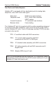
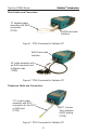
Test-Um NT955 Series ValidatorTM Introduction Data Cables and Connection 12” shielded cable assembly with RJ45 connectors (TP55) RJ45 8-wire data interface Figure 1. TP55 Connected to Validator-NT RJ45 8-wire data interface 24” cable assembly with an RJ45 connector and 8 alligator clips (TP68) Figure 2. TP68 Connected to Validator-NT Telephone Cable and Connection 7.
Test-Um NT955 Series ValidatorTM Introduction Two Wire and Connections “F” connector coax interface 3’ RG6 video coaxial cable (not included) Figure 4. Video Coaxial Cable Connected to Validator-NT “F” connector coax interface Adapter, BNC plug to F Jack (TP62) RG59/U Coaxial cable with BNC connectors (not included) Figure 5. Security Cable Connected to Validator-NT Banana Jacks 2-wire testing Banana Jacks to alligator clip cable assembly (not included) Figure 6.
Test-Um NT955 Series ValidatorTM Introduction Data Cable & Remote Connection Figure 7.
Test-Um NT955 Series ValidatorTM Introduction Registration You must register your product with Test-Um Inc. to be eligible to receive firmware and software updates, as well as important product announcements, helpful hints and other support services. To register, go to our web site at www.test-um.com and click on Warranty Registration or fill out the enclosed warranty registration card completely and mail it immediately.
Test-Um NT955 Series ValidatorTM Introduction Support Information Post-sale Technical support is available Monday through Friday 8:30 am to 4:30 p.m. Online technical assistance is available via our web site at www.test-um.com by selecting Validator-NT from the Home screen and clicking Contact Us. You may send e-mail to support@test-um.com or click Live Chat to communicate real time with our Technical Support department via instant messaging.
Test-Um NT955 Series ValidatorTM Introduction Tests Performed Validator-NT performs specified tests that produce PASS or FAIL results on a wide range of standard cables. In addition, a Bit Error Rate Test (BERT) is performed to determine the actual speed capabilities of CAT 5, CAT 5E, and CAT 6 network cables. A green check mark with VoIP indicates the cable is certified to support a data rate of 100 Megabit or greater, which is a basic requirement for VoIP applications.
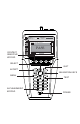
Test-Um NT955 Series ValidatorTM About Your Validator-NT About Your Validator-NT Main Unit Features 13 11 12 14 17 19 10 VALIDATOR-NT TM 16 15 8 18 5 6 QUIT T ACCP SEL 3 MENU 2 7 TEST 1 2 ABC 3 DEF GHI 4 5 6 MNO PRS 7 8 TUV 9 WXY * 0 QZ # JKL 4 9 1 21 20 Figure 8.
Test-Um NT955 Series ValidatorTM About Your Validator-NT . Table 1. Main Unit Features Item Feature Description Power Key is pushed to power unit on/off. When unit is on a short tap changes the backlight from dim to bright. Holding key down for over a second turns the unit off. 1 Menu Key opens a shortcut window of simple functions. 2 MENU 3 ACCP 4 QUIT Quit Key exits the current selections or moves backup in the menu sequence.
Test-Um NT955 Series ValidatorTM About Your Validator-NT Table 2. Main Unit Features (Cont.) Item Feature 10 Display 11 Data Jack 12 13 14 15 4 inch LCD color screen. RJ45, 8 wire data interface, T568A/B pairing. Telephone Jack RJ11, 6 Wire Telco interface, USOC pairing.
Test-Um NT955 Series ValidatorTM About Your Validator-NT Remote Unit Features 7 8 5 6 1 2 9 LINK VALIDATOR REMOTE TM CHARGE 76~100 50~75 25~49 5~24 LOW MADE IN USA 4 BATTERY STATE 3 10 11 Figure 9.
Test-Um NT955 Series ValidatorTM About Your Validator-NT Table 3. Remote Unit Features Item Feature Description 1 Link LED Turns on when a link is established with another network device. 2 Charge LED Battery is charging when LED light is blinking. 3 Battery state When selected the battery life capacity is shown.
Test-Um NT955 Series ValidatorTM About Your Validator-NT Standard Accessories NT955 Validator-NT™ NT940 Plan-Um™ Software (2) NT93 Lithium-ion Rechargeable Batteries (2) TP55 12” Cable Assemblies, Shielded RJ45 Connectors NT928 Validator-NT™ Remote NT95 Cable Labels (2) NT92 AC Adapter, Charger Units (2) TP20 7.
Test-Um NT955 Series ValidatorTM About Your Validator-NT Standard Accessories (Continue) (2) TP62 Adapters, BNC Plug to F Jack (2) TP74 Sacrificial Cables for Extending Modular Plug Optional Accessories NT935 Validator Main Unit Carrying Case 21 TP610 Set of 8 Wiremap Remotes
Test-Um NT955 Series ValidatorTM About Your Validator-NT Menu Options & Navigation Soft Keys – Defines functions specific to the current screen. VALIDATOR-NT TM Arrow Keys – are used to navigate up, down, right, or left between cells, words or spaces. Job Manager 2005 Aug 25 Test-Um Inc. 10:53:01 validator 100% Untitled1.job File Name Modified Magicworld.job 13.17 Tue 2005 Oct 05 13 K Test-um.job 10.21 Wed 2005 Oct 06 25.1 K Technicolor.job 9.51 Fri 2005 Oct 08 11.7 K Untitled1.job 10.
Test-Um NT955 Series ValidatorTM Battery and Power Management Battery and Power Management The lithium-ion rechargeable batteries (NT93) included with the ValidatorNT main unit and remote are recharged any time the Validator-NT or remote are connected to the AC adapters included in the Validator-NT kit. Use of other adapters, particularly car adapters, should always be avoided. The batteries continue to charge during operation.
Test-Um NT955 Series ValidatorTM Battery and Power Management Validator-NT Main Unit When powered on, the Validator-NT reports the charging status at the top of the screen under the battery icon. A green full battery icon indicates the battery is fully charged. As the battery discharges, the percentage of remaining charge is displayed in 10% steps. The battery icon changes from green to amber when the battery reaches approximately 30% of its charge capacity.
Test-Um NT955 Series ValidatorTM Battery and Power Management Validator-NT Remote Unit The Remote unit has a battery charge indicator light that is on solid during rapid charge, blinks slowly while topping off, or is off when charging is completed. The 76-100% light will be on to indicate a fully charged battery. The remote unit displays the percentage of charge remaining in 25% increments. If no lights are on while powered by an AC adapter, the battery is not inserted.
Test-Um NT955 Series ValidatorTM Battery and Power Management Battery Lock Feature A Battery Lock feature on the main and remote Validator-NT units is designed to prevent accidental ejection of the battery. Apply pressure with your thumb to slide the Battery Lock lever across the channel to secure the battery in the locked position (see Figure 11) and in the opposite direction to unlock the Battery Release button (see Figure 12). Press the Battery Release button to eject the battery.
Test-Um NT955 Series ValidatorTM Operations Operations The Validator-NT main unit is powered on by pressing the red power button. When powering on, the unit will display a series of start up screens until the Start screen is reached, which contains the main menu. At the top of every screen the following information appears - The name of the screen being displayed “Start, Auto Test” etc., the current job name, the battery condition and the date/time from the internal clock.
Test-Um NT955 Series ValidatorTM Operations Network Tests Selecting this button takes you to a menu of three manual tests that report the condition of the cable and verify connectivity to network devices. They are Port Discovery, Ping Test, and Hub Flash. Test Results cannot be saved. Port Discovery: Identifies an Ethernet connection and reports pertinent information including speed of the link, type of link (MDI, MDI-X or Auto MDI/MDI-X), Signal to Noise Ratio and Skew (if over 1000 Megabit).
Test-Um NT955 Series ValidatorTM Setting Up the Test Tool 1. Setting Up the Test Tool The Setup menu allows the user to adjust internal functions such as Display Contrast, the internal time clock, English or Metric units, the displayed language, and Shutdown Timeouts. Most of these functions can be set once and left alone unless a specific change is desired.
Test-Um NT955 Series ValidatorTM Setting Up the Test Tool 1.1. Display Contrast The Validator-NT main unit allows contrast settings for different environments. Use the + (F1) soft key to increase the contrast for a dark environment or – (F2) soft key to decrease the LCD contrast in a bright environment (see Figure 1.2). Set LCD Contrast Untitled1.job + 100% 2005 Aug 25 Test-Um Inc. 10:53:01 validator - Figure 1.
Test-Um NT955 Series ValidatorTM Setting Up the Test Tool 1.2. Printer Settings Select Printer Settings (see Figure 1.3). A pull down menu appears which displays common Bit Rates for printers. The Bit Rate you select must match the Serial Port Printer properties of the printer you use. Press Save (F1) to set and exit Printer Settings. Use the serial port on the left side of the Validator-NT to connect to the printer. A Cable Assembly is not provided. Printer Untitled1.
Test-Um NT955 Series ValidatorTM Setting Up the Test Tool 1.3. Shutdown Timeouts A Power Save mode is installed in Validator-NT to conserve battery life (see Figure 1.4). When the pre-set time limit is reached without any key input the main unit screen will begin to blink. Pressing any key will bring back the full screen and reset the timer.
Test-Um NT955 Series ValidatorTM Setting Up the Test Tool 1.4. Set the Clock using the Real Time Clock Screen Using the drop down dialog boxes, select the current year, month, day, hour, and minute (see Figure 1.5). Press Accept to select your choice and move to the next field. Press Set (F1) to confirm your choices and return to the Setup Screen. Real Time Clock Untitled1.job Year: Month: 2005 Aug 25 Test-Um Inc. 10:53:01 validator 100% 2005 August Day: 25 Hour: 10 Minute: 53 Set Figure 1.
Test-Um NT955 Series ValidatorTM Setting Up the Test Tool 1.5. Localization Using the drop down dialog box, select Metric or English units to report length measurements (see Figure 1.6). Press Accept. Press OK to confirm your choice and return to the Setup screen. Units Untitled1.job 100% Current Unit: 2005 Aug 25 Test-Um Inc. 10:53:01 validator English English Current Language: OK Figure 1.
Test-Um NT955 Series ValidatorTM Setting Up the Test Tool 1.6. Calibrate The calibration procedure is performed to set a reference point for cable length to 0 feet/meters. Once calibration is performed, the test unit retains the information. The Validator-NT does not require any other calibration. (Figure 1.7) Note: Please disconnect all Patch Cables Calibrate Untitled1.job 100% 2005 Aug 25 Test-Um Inc. 10:53:01 validator To calibrate the unit make sure there are no cables plugged into the unit.
Test-Um NT955 Series ValidatorTM Properties 2. Validator-NT Properties The Properties menu displays buttons that contain internal information on the state of charge associated with the battery, product revision levels, available free space on the Compact Flash card, and Test-Um support information. (Figure 2.1) Properties Untitled1.job 100% 2005 Aug 25 Test-Um Inc. 10:53:01 validator Battery Info Product Version CF Card Usage Support Info Figure 2.
Test-Um NT955 Series ValidatorTM Properties 2.1. Battery Info This screen indicates whether the unit is operating on Battery Power or External Power and displays information that allows the user to monitor the remaining charge status and aging of the battery. (Figure 2.2 & Figure 2.3) Charge Remaining: Displays the percentage of charge remaining in percentages ranging from 0% to 100%. As the battery discharges, the percentage of remaining charge is reported in 10% steps.
Test-Um NT955 Series ValidatorTM Properties Battery Properties 100% Untitled1.job 2005 Aug 25 Test-Um Inc. 10:53:01 validator BATTERY POWER Charge Remaining - 100% Status - Normal Serial Number - 3462150 Charge cycles --1 Remaining Maximum Capacity - 100% Total Charge Accumulated - 2 RST CHRG Figure 2.2 Unit Operating on Battery Power Battery Properties 100% Untitled1.job 2005 Aug 25 Test-Um Inc.
Test-Um NT955 Series ValidatorTM Properties 2.2. Product Version This screen displays the product’s electronic serial number plus the revision levels of the hardware, firmware and software in the ValidatorNT (See Figure 2.4). Should you require technical assistance you may be asked to refer to this screen to confirm current product revision information. This screen will also be important in managing future product upgrades and updates. Revisions Untitled1.job Component 100% 2005 Aug 25 Test-Um Inc.
Test-Um NT955 Series ValidatorTM Properties 2.3. Compact Flash Card Usage The Validator-NT kit includes a high quality mass storage compact flash card. Approximately 6000 cable tests can be stored per 32 Megabytes of card space. Press Select to view a pie chart that displays free card space with numeric values for percentage and kilobytes available (See Figure 2.5).
Test-Um NT955 Series ValidatorTM Properties 2.4. Support Info The Support Screen displays Technical Support contact information, including our web site, telephone number, and e-mail address. The NT955 Technical Reference Manual is available at www.test-um.com. In addition a blue box titled Manage Firmware displays which you will be able to select in the future to download product revisions from our web site. Specific update procedures will be included with the update file. 1.
Test-Um NT955 Series ValidatorTM Properties 6. Select the firmware file from the Firmware Package list. Press the Install soft key (F1) to install the firmware. (Figure 2.7) Manage Firmware Untitled1.job 100% 2005 Aug 25 Test-Um Inc. 10:53:01 validator Firmware Package VAL-full-02.03.TUI INSTALL Figure 2.7 Firmware Manager 7. The Firmware Revisions screen will show the new revision in the Now column. It also shows the minimum revision level necessary for compatibility with the new component. 8.
Test-Um NT955 Series ValidatorTM Managing Job Files 3. Managing Job Files The Job Manager screen is used to view a list of all job files stored on the compact flash (CF) card. Use the up and down arrows to highlight the job entry of interest. The soft keys are labeled with the functions that can be performed on the currently highlighted job: Open, Copy, Rename, or Delete. (Figure 3.
Test-Um NT955 Series ValidatorTM Managing Job Files Press the OPEN (F1) soft key to open the selected job. Opening the job will switch you to the Auto Test screen where the Cable Test Schedule displays all of the cable runs associated with the selected job. Note: If there is unsaved data from the currently selected job, a pop-up window displays providing the option to save the current job. The COPY (F2) soft key is used to make an exact copy of the highlighted job with a different name.
Test-Um NT955 Series ValidatorTM Managing Job Files The Job Utilities screen provides the ability to create new jobs and template (*.Tut) files as well as the Save As function to save the current job information in memory under a different job name. From the Start screen, select Auto Test, and use the right arrow key to scroll to Job Utilities. The Save command on this screen is the same as the save in the Menu Window, which saves the current RAM memory contents to the currently loaded job’s file.
Test-Um NT955 Series ValidatorTM Managing Job Files 3.1. Creating A New Job Creating the job in Plan-Um and uploading it to Validator-NT is generally the quickest and easiest method of preparing your Cable List for testing. Only Test Results associated with a job can be saved and downloaded to Plan-Um for printing and archiving. Start Auto Test Manual Tests Network Tests Job Manager Setup Properties New File Filename: Cable Test Schedule 2005 Aug 25 Test-Um Inc.
Test-Um NT955 Series ValidatorTM Managing Job Files 3.2. Creating Job Information Job Information consists of Contractor Information and Site Information. Contractor Information identifies contact information for the company performing the job. Site information contains information about the site you are designing. (Figure 3.4) Site and Contractor information prints on all job reports, and is used for bidding and invoicing. 1. Select Auto Test from the start screen. 2.
Test-Um NT955 Series ValidatorTM Managing Job Files 3.3. Creating Template Information The purpose of the Template file (*.tut file) is to avoid reentering Company Information and/or Custom Cable Definitions for each job by saving the information in a Template that can be used on multiple jobs. You can also use an existing Job to create a Template. Test-Um recommends creating one or more reusable Template files (*.tut files) when you perform the initial setup on your Validator-NT.
Test-Um NT955 Series ValidatorTM Managing Job Files 3.4. Using Template Files Each time you create a New Job, select a previously created template with Contractor Information and/or Custom Cable Definitions to avoid reentering information. (Figure 3.6) 1. From the Start screen, select Auto Test. 2. Using the arrow key, navigate to Job Utilities and press Select. 3. On the Job utilities screen, select New. 4. Enter a name for your job in the Filename box using the alphanumeric keypad. Press Accept.
Test-Um NT955 Series ValidatorTM Managing Job Files 3.5. Step By Step Instructions for Creating a New Job 1. From the Start screen, select Auto Test. 2. Using the arrow key navigate to Job Utilities and press Select. 3. On the Job Utilities screen, select New. 4. Enter a Filename using the alphanumeric keypad. (Figure 3.3) Press Accept. Depress the respective key multiple times to scroll through the alpha and numeric options.
Test-Um NT955 Series ValidatorTM Managing Job Files 11. When all fields have been completed, press Quit. The Auto Test screen reappears. 12. Select Cable Test Schedule. Using the alphanumeric keypad create a Test Schedule by completing the Cable ID field and selecting a Cable Type from the drop down menu. The To and From fields are optional information. The Result field is automatically populated when tests are run on that cable. 13. Proceed to Test by connecting the appropriate cable assembly.
Test-Um NT955 Series ValidatorTM How AutoTest Works 4. How Auto Test Works Creating the Cable Test Schedule in Plan-Um, uploading it to the Validator, and running Auto Test is the easiest and most efficient way to verify cables. See the Uploading/Downloading Jobs section of this manual (or the Plan-Um Software Instructions) for detailed instructions on how to upload and download job information and test results between Plan-Um and the Validator.
Test-Um NT955 Series ValidatorTM How AutoTest Works Current Job 2005 Aug 25 Test-Um Inc. 10:53:01 validator 100% Untitled1.
Test-Um NT955 Series ValidatorTM How AutoTest Works 4.1. Cable Test Schedule The Cable Test Schedule displays all the individual cable runs associated with the open job. For your convenience when testing, you can sort each field in the Cable Test Schedule in ascending or descending order. To sort the Cable Test Schedule, move the highlight to a cell in the column to be sorted and press the SORT (F4) soft key. The column is sorted first in ascending order.
Test-Um NT955 Series ValidatorTM How AutoTest Works A PASS or FAIL indication will be briefly displayed along with a speed rating up to 1 Gigabit depending on the cable type. The screen will show the Remote ID, wiremap of the individual pairs, and automatically scroll down to display Length, Skew, SNR and BERT test results. The lights on the remote unit flash sequentially to indicate a PASS condition. The job file is saved after every Auto Test.
ValidatorTM How AutoTest Works Test-Um NT955 Series Test Results Untitled1.job 2005 Aug 25 Test-Um Inc. 10:53:01 validator 100% Length Max: 300ft 184ft A 188ft B Short 7 ft C 186ft D Skew Max: 35ns SNR Min:20db -- 30.0 -- 30.0 -- -- -- -- BERT Results: BACKSPC PG UP PG DOWN Figure 4.4 Page Down to Display Distance To Short Miswire - A wire or both wires of a pair are not connected to correct pins at the other end of the cable.
ValidatorTM How AutoTest Works Test-Um NT955 Series Test Results Untitled1.job 100% 2005 Aug 25 Test-Um Inc. 10:53:01 validator Length Max: 300ft A Split 188ft B C Split D 186ft Skew Max: 35ns SNR Min:20db -- -- -- -- -- -- -- -- BERT Results: BACKSPC PG UP PG DOWN Figure 4.6 Test Results-Split Auto Find Feature: It is necessary to connect the Validator-NT remote unit to the other end of the cable to measure for both Speed and Performance.
ValidatorTM How AutoTest Works Test-Um NT955 Series 4.2. Site Info The next button on the Auto Test sub-menu is Site Info. This button displays the Customer Contact Information associated with the job you have selected for testing. By highlighting and selecting a field you can update or change the information in each field, i.e.; Job ID, Contact name, etc. Press Accept to accept the changes that were made and exit that field. To save text press Menu, scroll to Save Job, and press Select.
ValidatorTM How AutoTest Works Test-Um NT955 Series 4.4. Custom Cable Definitions The Custom Cable Definitions screen shows all defined cable types loaded into the Validator-NT from the current job and what category of test is performed on each type. The soft keys, F1 thru F3, allow for adding, editing, and deleting cable information. (Figure 4.10) The recommended procedure is to create Custom Cable Definitions in Plan-Um and upload them to Validator-NT.
ValidatorTM How AutoTest Works Test-Um NT955 Series 8. To save the custom test parameters you have entered, press the Save Type soft key (F3). 9. A message box appears that asks you to confirm the changes in the test parameters you have entered. If you are sure of the changes press Yes. To verify or edit or changes, repeat steps 4 through 7.
ValidatorTM How AutoTest Works Test-Um NT955 Series Type Table Screen Type Name Category Default CAT5 Data Yes CAT5E Data Yes CAT6 Data Yes CAT3_4P Phone Yes CAT3 Phone Yes CAT3_2P Phone Yes RG-6 2 Wire Yes Fire 2 Wire BACKSPC NEW Test Definitions 100% Data Type Data Test Parameters 100% Speed: None Mx Lngth( ft ): SNR: Connector: DELETE 2005 Aug 25 Test-Um Inc. 10:53:01 validator Phone Type Two-Wire Type Two Wire Test Parameters 100% Untitled1.
Test-Um NT955 Series ValidatorTM How AutoTest Works 4.5. Job Utilities The last button on the Auto Test menu is Job Utilities. This screen has buttons to allow creation of a new job file, open an existing job file on the CF card, export a template file, save the file that is currently open, or save an open file as a file with a new name (Figure 4.11) Job Utilities Untitled1.job 100% 2005 Aug 25 Test-Um Inc. 10:53:01 validator Open New Save As Save New File 2005 Aug 25 Test-Um Inc.
Test-Um NT955 Series ValidatorTM Running Manual Tests 4.6. Step by Step Instructions for Performing Auto Tests 1. From the Start Menu, navigate to the Job Manager using the arrow keys which move from left to right on each row. 2. Select the Job you wish to test. Press Open. 3. The Auto Test screen is presented with the Cable Test Schedule button highlighted. Press Select to view the Test Schedule. Press the up and down arrows to highlight the cable to be tested. 4.
Test-Um NT955 Series ValidatorTM How AutoTest Works 10. Press the Results (F2) soft key to display detailed test information for the cable that is currently highlighted. 11. Pass test parameters display in green and fail parameters display in red. 12. Test Results are automatically saved to the current job. To save text changes, select Save Job. 13. Test Results for the selected job can then be downloaded to laptop/ PC and an End of Job Report generated for billing.
Test-Um NT955 Series ValidatorTM Running Manual Tests 5. Running Manual Tests Manual Tests performs individual tests on Data, Phone, or 2-wire cables based on defined test standards. The tests that can be performed for each selected cable type are listed on the Manual Test screen for that type (Figure 5.2). 5.1. Data Cables Data Cables are defined as cables wired to T568A/B pin numbering and pairing. Validator-NT will perform full Signal to Noise Ratio and Skew testing as part of the cable test.
Test-Um NT955 Series ValidatorTM Running Manual Tests Cable Tests 100% Untitled1.job Data Cable Data Manual Tests Hub Flash 100% 2005 Aug 25 Test-Um Inc. 10:53:01 validator Cable Test Tone Hub Flash BERT Test BERT Test 2005 Aug 25 Test-Um Inc. 10:53:01 validator 100% 2-Wire Cable Phone Cable Untitled1.job Untitled1.job 2005 Aug 25 Test-Um Inc. 10:53:01 validator 100% Untitled1.job 2005 Aug 25 Test-Um Inc.
Test-Um NT955 Series ValidatorTM Running Manual Tests 5.2. Phone Cables Phone Cables are defined as cables wired to the USOC 3 pair standard for pin numbering and pairing. The test shows opens, shorts and length of the run. The wiremap and length measurements are displayed. (Figure 5.3) Cable Tests 100% Untitled1.job Data Cable 2005 Aug 25 Test-Um Inc. 10:53:01 validator Phone Manual Tests 100% Untitled1.job 2005 Aug 25 Test-Um Inc. 10:53:01 validator Cable Test Wiremap - PHONE Untitled1.
Test-Um NT955 Series ValidatorTM Running Manual Tests 5.3. 2-Wire Cables 2-wire cables are tested for wire map and length. You can also send tone over the cable. (Figure 5.4) Cable Tests Untitled1.job 100% Data Cable 100% 2005 Aug 25 Test-Um Inc. 10:53:01 validator Cable Test 2 Wire Length Untitled1.job 100% Remote ID: 1 Tone 2 Wire Tone 2005 Aug 25 Test-Um Inc. 10:53:01 validator Untitled1.job 100% 2005 Aug 25 Test-Um Inc. 10:53:01 validator Length Constant: 15 PF/ft.
Test-Um NT955 Series ValidatorTM Running Manual Tests 5.4. Step by Step Instructions for Performing Manual Tests 1. From the Start Menu, select Manual Tests. Choose Data, Phone or 2-wire cable type. Warning! Manual Test Results will NOT be saved. 2. Using the appropriate cable assembly and jacks, connect the Validator-NT main unit to the cable identified in the Test Schedule with the Remote Unit connected to the opposite end. Cable Test 1. Select Cable Test to initiate a test sequence.
Test-Um NT955 Series ValidatorTM Running Manual Tests Placing Tone On a Cable Pair 1. Select Manual Tests. Choose Data, Phone or 2-wire cable type. 2. The Manual Test Menu for the cable type you selected displays. 3. Select Tone. 4. Select the desired Tone Sound. Press Accept. The cursor moves to the Tone Path dialog box. (Figure 5.6) 5. Select the Tone Path by choosing the cable pair or pairs you wish to apply Tone to. Press Accept. 6.
Test-Um NT955 Series ValidatorTM Running Manual Tests Testing Cable Length When you run Cable Test, length is reported in feet or meters. In addition, the Manual Cable Test for data includes a quick independent length test using the Length (F1) soft key. This test is useful to the installer to determine how much cable is left on the reel or the length of a cable run. Follow the procedure for Cable Tests described above. (Figure 5.7) 1. Select Manual Tests. Choose Data, Phone or 2-wire cable type. 2.
Test-Um NT955 Series ValidatorTM Running Manual Tests Hub Flash Test This test sends a link signal to test for active Ethernet equipment. This is the only test that runs with other Ethernet equipment. 1. From the Data Manual Test screen, select Hub Flash 2. From the drop down menu, select a specific data rate or Any if you wish to have the hub and Validator-NT auto negotiate the speed. (Figure 5.8) 3.
Test-Um NT955 Series ValidatorTM Running Manual Tests Performing a Bit Error Rate Test A Bit Error Rate Test (BERT) sends data packets from the main unit to the remote, measures speed and errors and correlates this to a PASS or FAIL result. This test can only be run from end to end on a single cable, it cannot be run through an Ethernet hub or switch. 1. From the Data Manual Tests screen, select the BERT Test button. (Figure 5.9) 2.
Test-Um NT955 Series ValidatorTM Network Tests 6. Performing Active Network Tests Active Network Tests include four functional test areas designed to report cable performance and verify connectivity to network devices: Port Discovery, Ping, Cisco Discovery Protocol, and Hub Flash. Select Network Tests from the Start menu to access Network Tests. Use the RJ45 ports to perform these tests. Warning! Active Network Test Results will NOT be Saved. Start 100% Untitled1.job 2005 Aug 25 Test-Um Inc.
Test-Um NT955 Series ValidatorTM Network Tests 6.1. Port Discovery Port discovery identifies telephone or network devices connected to the other end of the jack or cable. The test begins with a search for voltages that may be present. If voltages are found, the patterns for commonly used services are compared to the voltages observed and reported as phone, ISDN or legacy phantom power as appropriate. If the voltage pattern is unknown, the port pin conditions are reported. Port Discovery Untitled1.
Test-Um NT955 Series ValidatorTM Network Tests Port Discovery 2005 Aug 25 Test-Um Inc. 10:53:01 validator 100% Untitled1.job ISDN ISDN 1 2 3 4 5 6 7 8 . + . + . 6.3 ISDN Phone Detected Port Discovery 2005 Aug 25 Test-Um Inc. 10:53:01 validator 100% Untitled1.job Legacy Power over Ethernet PoE 1 2 3 4 5 6 7 8 . + . + . 6.
Test-Um NT955 Series ValidatorTM Network Tests If no telephone or voltage sources are found, Validator-NT attempts an Ethernet link.
Test-Um NT955 Series ValidatorTM Network Tests If neither voltages nor Ethernet is detected, Validator-NT searches for its remote to run a cable test. If the remote is found, a manual mode cable test is run and the remote ID, wiremap, full Signal to Noise Ratio, and Skew test results (1000Mbit only) are displayed. Speed testing, as well as placing tone on a cable, is performed in the Manual Test mode of the Validator-NT only.
Test-Um NT955 Series ValidatorTM Network Tests 6.2. Ping Test The Ping Test is used to verify connectivity to resources on or off the network and IP addresses. The Ping Test will simultaneously Ping up to seven different IP addresses and can be run in DHCP or manual addressing modes. In DHCP mode, the Validator-NT’s assigned address and the addresses of the router/gateway and DNS server plus the net mask are obtained automatically from a DHCP server and the values displayed on the Validator-NT.
Test-Um NT955 Series ValidatorTM Network Tests For manual IP addresses, uncheck the DHCP mode box by pressing the up and down arrow keys to highlight the DHCP box and press Select to deselect DHCP mode. Use the arrow keys to highlight the My IP, Gateway Router (GWRTR) and Domain Name Server. Edit these fields as necessary using the keypad, Backspace (F1) and Delete (F2) soft keys. Press Accept to confirm your current selection and move to the next field.
Test-Um NT955 Series ValidatorTM Network Tests The Ping Targets must also be set manually. To change the IP targets, press the Targets soft key (F4) and edit these fields as necessary using the keypad, Backspace (F1) and Delete (F2) soft keys. The www.com soft key (F3) is used as a shortcut to add the common “www.” prefix and the “.com” suffix to an entered name. Pressing the F3 soft key would change “Test-Um” to “www.Test-Um.com”. When entering addresses, the * button is a shortcut for the period (.
Test-Um NT955 Series ValidatorTM Network Tests The Ping Tool soft key (F3) only shows on the IP address screen once valid DHCP information or manual IP addresses are configured. All the IP addresses that are currently setup to be pinged are displayed on entry. Uncheck the box next to any addresses you do not want to ping. The Host/IP address can be edited directly on this screen (the default URL is www.test.um.
Test-Um NT955 Series ValidatorTM Network Tests You can increase the length of the data packet used to ping by highlighting the target IP Address and using the right arrow key to highlight the word Long. Press Select to toggle the size of the data packet between normal and long. Ping Tool 100% Untitled1.job PING Target 2005 Aug 25 Test-Um Inc. 10:53:01 validator Size Received/Sent HOST/IP www.Test-Um.com Long GW/RTR 192.168.1.1 Long DNS Long 192.168.1.100 HOST/IP www.yahoo.
Test-Um NT955 Series 6.3 Cisco Delivery Protocol This feature detects Cisco Delivery Protocol (CDP) messages broadcast by Cisco bridges and routers over the network to inform each other of their existence. The content of the CDP message contains addresses that SNMP messages can be sent to. Network Tests Untitled1.job 100% 2006 Jul 05 Test-Um Inc. 10:53:01 validator Port Discovery Ping Test Cisco Discovery Protocol Hub Flash 6.
Test-Um NT955 Series To view Cisco Delivery Protocol broadcast messages 1. From the Start Menu, select Network Tests. Select Cisco Delivery Protocol. 2. Use a patch cable to connect the Validator-NT main unit to the network or device port to be monitored for CDP. 3. CDP information automatically displays and a message “Reading CDP packets from network” appears on your screen below the CDP message. CDP Display Screen Untitled1.job 100% 2006 Jul 05 Test-Um Inc.
Test-Um NT955 Series 4. To clear the current broadcast, press the Clear soft key (F1). The screen goes blank. CDP Display Screen Untitled1.job 2006 Jul 05 Test-Um Inc. 10:53:01 validator 100% Reading CDP packets from network. BACKSPC CLEAR START STOP 6.16 Selecting Clear for CDP Display Screen 5. To start a new broadcast, press the Start soft key (F2). The message “Reading CDP packets from network” appears on your screen below the CDP message. 6.
Test-Um NT955 Series ValidatorTM Network Tests 6.4. Hub Flash Hub flash sends an intermittent link signal to flash the link status light on Ethernet equipment. You can select a specific data rate or Any if you wish to have the hub and the Validator-NT auto negotiate the speed. Hub Flash 100% Untitled1.job 2005 Aug 25 Test-Um Inc. 10:53:01 validator Select Rate: Any O NIC Wiring: Auto Flash Any, Auto FLASH 6.
Test-Um NT955 Series ValidatorTM Network Tests 6.5. Step by Step Instructions for Performing Network Tests 1. From the Start Menu, select Network Tests. Choose Port Discovery, Ping Test or Hub Flash. Warning! Network Test Results will NOT be saved 2. Use a patch cable to connect the Validator-NT main unit to the jack or network device to be tested. Port Discovery 1. From the Start menu, navigate to Network Tests using the arrow keys which move from left to right on each row. 2.
Test-Um NT955 Series ValidatorTM Network Tests Ping Test 1. Select Ping Test. 2. Press Select to begin DHCP request (DHCP box checked) or to Configure IP addresses in manual address mode (box unchecked). In manual address mode, be sure the displayed addresses are appropriate for the network being tested. If not, use the keypad, Backspace (F1) and Delete (F2) soft keys to edit My IP Address, Gateway Router (GWRTR) and Domain Name Server (DNS). 3.
Test-Um NT955 Series ValidatorTM Network Tests Hub Flash 1. Select Hub Flash. 2. From the drop down menu, select a specific data rate or Any if you wish to have the hub and the Validator-NT auto negotiate the speed. Press Accept. 3. In 10Mb or 100 Mb mode, the Validator-NT can be set to emulate a NIC, a HUB or an Auto mode (auto MDI/MDIX) device using the drop down menu. If plugging into a hub, the Validator-NT must be set to NIC or Auto modes.
Test-Um NT955 Series ValidatorTM Uploading/Downloading Jobs 7. Uploading/Downloading Jobs 7.1. Uploading the Cable Test Schedule to the Validator-NT Open the My Documents folder on your desktop. Right click the PlanUm job you want to transfer, and select Copy. Power the Validator on. Open the My Computer folder on your desktop. Plug the USB cord into the USB port on your PC and into the ValidatorNT (Figure 6.1).
Test-Um NT955 Series ValidatorTM Uploading/Downloading Jobs 7.2. Downloading Test Results from Validator-NT to Plan-Um Open the My Computer folder on your desktop. Power the ValidatorNT on. Plug the USB cord into the USB port on your PC and into the Validator-NT (Figure 7.1). As the connection is made, the drive the Validator is mapped to (usually Local Disk E:) appears on your desktop and the message “USB – File I/O Mode” appears in red on the Validator.
Test-Um NT955 Series ValidatorTM Archiving /Saving Test Results 8. Archiving/Saving Test Results To save, press Menu. Use the Up Arrow key to highlight Save Job and press Select to save your Test Results to the flash memory card. (Figure 8.1) Test Results Cable001 Pass Test Time: 10/11/2004 10:53 A.
Test-Um NT955 Series ValidatorTM Printing Test Results 9. Printing Test Results The most efficient method to print job reports is to download test results to a pc/laptop. See Uploading/downloading Jobs. Future upgrades may permit the user to print Test Results directly from the Validator-NT to a serial port printer using a D-Sub 9 pin Male to Female cable assembly. (Figure 9.1) Validator-NT Serial Port D-Sub 9 pin Male to Female Cable Assembly Figure 9.
Test-Um NT955 Series ValidatorTM Application Notes 10. Application Notes for Typical Field Use 10.1. New Job, New Cable Installations 1. A Layout using the Plan-Um software will be created conforming to the customers’ facility or residence and a job id created. 2. Cables will be chosen and run between agreed upon ports and a Comm. Panel or Patch Panel. 3. Check Cable Test Schedule against the Layout to make sure all ports are connected correctly. 4.
Test-Um Inc. The Intelligent Test Solutions Company 808 Calle Plano Camarillo, CA 93012 (805) 383-1500 / FAX (805) 383-1595 www.Test-Um.