TerraWave Solutions® 9’ Site Survey Extension Pole Installation Instructions Version 1.4 - Page 1 www.terrawave.com Email: sales@terrawave.
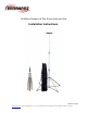
Introduction TerraWave’s 9’ Site Survey Extension Pole is used during a professional site survey to assist system engineers with a convenient way to raise an access point (AP) and antenna to an extended height without the need and use of a ladder. The maximum height of the site survey extension pole is 9 Feet. Before assembling this product, read these instructions carefully. Failure to follow these instructions could lead to damage to the product or cause hazardous conditions.
Precautions Read and understand all instructions before you begin assembling the unit. When assembling and using this product, basic safety precautions and considerations should always be followed to reduce the risk of personal injury. Do not leave unattended at any time. Exercise caution when using this product outdoors or around electrical wiring as there is a potential for electrical shock. Do not use liquid cleaners or aerosol cleaners. Use a damp cloth for cleaning.
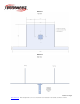
2. Affix the extension pole mounting bracket to the top of the pole. Secure the extension pole mounting bracket with the 4 screws included. Screws Secure Mounting Plate in Place Each extension pole kit is supplied with a mounting plate to be used for attaching WLAN/Networking components. The diagrams on the following pages show detailed dimensions of the mounting plate and hole configuration. Version 1.4 - Page 4 www.terrawave.com Email: sales@terrawave.
Diagram 1 Diagram 2 Version 1.4 - Page 5 www.terrawave.com Email: sales@terrawave.
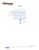
Diagram 3 Version 1.4 - Page 6 www.terrawave.com Email: sales@terrawave.
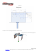
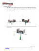
Diagram 4 3. Attach the AP’s mounting bracket with the included screws. Displayed with a Cisco AP 1242 Mounting Bracket Version 1.4 - Page 7 www.terrawave.com Email: sales@terrawave.
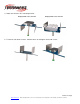
4. Attach the AP to the AP’s mounting bracket. Displayed with a Cisco AP 1242 Displayed with a Cisco AP 1252 5. To lock the side wings in place, hold the wings up and tighten the thumb screws. Version 1.4 - Page 8 www.terrawave.com Email: sales@terrawave.
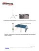
6. Antenna Attachment: a. Depending on the type of antenna being used, users can use the hardware that came with the antenna (i.e. hose clamp) or just attach with a zip tie (not included). Please note that mounting brackets/fasteners to attach the antenna to the mounting plate are not included in either site survey extension pole kit. b. For ceiling mount antennas, attach the clips (if not done already) and clip onto the side bar of the mounting plate. Version 1.4 - Page 9 www.terrawave.
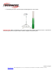
7. Extend the pole to the desired height and hand-tighten the green knobs. Important Note: When extending the pole, turn the green knobs counter-clockwise to loosen, extend to the desired height and turn the green knobs clockwise to tighten and hold in place. Version 1.4 - Page 10 www.terrawave.com Email: sales@terrawave.