
Operation and maintenance manual


Section 250-0090
Braking System - Directional Control Valve
SM 2254 11-03
2
SM - 2311SM - 2310
movement under the influence of compressed spring
(7) links port 'B' to port 'T' permitting a controlled bleed
down of the applied service brakes to tank at port 'T'.
This controlled bleed down permits a synchronised
service brake release/mechanical park brake
application. Refer to Section 250-0000, BRAKING
SYSTEM SCHEMATIC.
Note: With engine shutdown, brake manifold valve
pressure is dead headed at ports 'P' and 'A'.
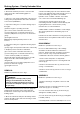
Refer to Fig. 3. When the engine is running,
transmission hydraulic pilot pressure enters the
directional control valve through port 'a'. Spool (3) is
pushed by this pressure and compresses spring (7) on
port 'b' side of directional control valve. This movement
internally links port 'P' to 'B' in sub plate (13).
With transmission pilot pressure operating at port 'a',
the directional control valve (energised) has an open
circuit between the brake manifold valve and port 'Px'
in the treadle valve. This permits a flow of oil to either
energise the 'Px' port at the treadle valve, or, exhaust
the 'Px' port through the manifold block to tank,
dependant on operation of the brake manifold valve.
The brake manifold valve is controlled by the park/
emergency control switch.
Port 'b' is connected as a drain to tank to prevent
excess oil forming a hydraulic lock within the
directional control valve. This could result in erratic
park brake operation.
REMOVAL
WARNINGS
To prevent personal injury and property
damage, be sure wheel blocks and blocking
materials are properly secured and of
adequate capacity to do the job safely.
Hydraulic fluid pressure will remain
within the system after engine shut down.
Operate the treadle pedal continuously until
the pressure has dissipated before carrying
out any work on the braking system or serious
injury could result.
1. Position the vehicle in a level work area, apply the
parking brake, switch off the engine and turn steering
wheel in both directions several times to relieve any
pressure in the steering circuit.
2. Operate the treadle valve continuously to relieve
pressure in the braking system. Block all road wheels
and place battery master switch in the 'Off' position.
3. Remove mounting hardware securing cover plate
to cradle assembly at the rear of the cab. Remove
cover plate to gain access to directional control
valve.
4. Ensure all hydraulic lines connected to the
directional control valve are identified for ease of
installation and, with suitable containers available to
catch leakage, disconnect hydraulic lines. Fit
blanking caps to all open lines and fittings.
Fig. 3 - Directional Control Valve - Energised
Fig. 2 - Directional Control Valve - De-energised
8
T
P
a
b
BA
TO 'Px' PORT
TREADLE VALVE
FROM BRAKE
MANIFOLD VALVE
8
T
P
a
b
BA
TO 'Px' PORT
TREADLE VALVE
FROM BRAKE
MANIFOLD VALVE