
Operation and maintenance manual


Section 250-0090
SM 2254 11-03
1
BRAKING SYSTEM - Directional Control Valve
DESCRIPTION
Numbers and letters in parentheses refer to Fig. 1.
The directional control valve can be identified as
item 8 in Section 250-0000, BRAKING SYSTEM
SCHEMATIC.
The directional control valve is mounted on the cradle
assembly at the rear of the cab alongside the brake
manifold valve. It is located in the 'Px' hydraulic
circuit between the brake manifold valve and the
treadle valve. The 'Px' circuit hydraulically actuates
the treadle valve when the park/emergency control
switch is activated. It also controls automatic service
brake applied pressure bleed down, with engine
shutdown.
The directional control valve assembly comprises of
a sub plate and valve body assembly. Hydraulic
connections to the directional control valve assembly
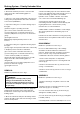
Fig. 1 - Directional Control Valve
are made as follows:
Valve Body Assembly
Port 'a' - Transmission pilot pressure
Port 'b' - Case drain to tank
Sub Plate
Port 'A' - Plugged
Port 'B' - To 'Px' port at treadle valve
Port 'P' - Supply line from brake manifold valve
Port 'T' - Tank return
OPERATION
Numbers in parentheses refer to Fig. 1. Figs. 2 and 3
are shown with brake manifold valve de-energized.
Refer to Fig. 2. Engine shutdown, park/emergency
control switch applied, results in a loss of transmission
pilot pressure at port 'a'. The resultant spool (3)
5 - Spring End Cap
6 - Slide Washer
7 - Spring
8 - Spacer
1 - Valve Body Unit
2 - End Cover
3 - Spool
4 - Spring End Cap
P
B
T
a
b
b
a
A
74981 5 710
6
3
11
12
11
2
3
6
13
9 - Allen Bolt
10 - Allen Bolt
11 - 'O' Ring
12 - 'O' Ring
13 - Sub Plate
SM - 2309