
Operation and maintenance manual


Section 250-0075
1
SM 2161 7-02
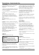
TO BRAKE
MANIFOLD VALVE
TO ENGINE
COOLING FAN
MOTOR
FROM TRIPLE
GEAR PUMP
3
1
2
DESCRIPTION
The priority unloader valve can be identified as item 10
in Section 250-0000, BRAKING SYSTEM
SCHEMATIC. Numbers in parentheses refer to Fig. 1.
Located on the right hand side of the hydraulic cradle,
the priority unloader valve comprises of an aluminium
body (3) with an integral check valve (2) and unloader
relief valve (1).
The priority unloader valve receives hydraulic supply
from the brake section of the triple gear pump. The
priority unloader valve controls pressure to the treadle
valve and the brake accumulators, via the brake
manifold valve. Refer to Section 250-0050, BRAKE
MANIFOLD VALVE.
OPERATION
Numbers in parentheses refer to Fig. 1.
Refer to Fig. 2. The priority unloader valve forms part
of the brake actuation circuit. Main hydraulic supply
pressure is delivered by the brake section (front
section) of the triple gear pump. The priority unloader
valve maintains pressure within the brake circuit to
170 bar (2465 lbf/in²). This is achieved by internally
sensing the pressure within the brake circuit. When
the system pressure is below the defined setting of
170 bar (2465 lbf/in²), the unloader relief valve (1)
connects the supply pressure to the brake manifold
valve by unseating the check valve (2), allowing the
brake accumulators to charge. When the brake circuit
pressure is attained, the unloader relief valve (1)
diverts supply pressure to engine cooling circuit to
supplement the engine cooling fan motor. The check
valve (2) is now closed, isolating the brake circuit.
FUNCTIONAL CHECK
Numbers in parentheses refer to Fig. 1.
The priority unloader valve, although adjustable,
should be preset to 170 bar (2465 lbf/in²). Refer to
following procedure for valve pressure check and
adjustment.
WARNING
Hydraulic fluid pressure will remain within the
system after engine shut down. Operate the
treadle valve continuously until the pressure
has dissipated before carrying out any work on
the braking system or serious injury could
result.
WARNING
To prevent personal injury and property
damage, be sure wheel blocks are properly
secured and of adequate capacity to do the job
safely.
1. Attach appropriate pressure gauge to the diagnostic
check point on the brake manifold valve (Port P1).
BRAKING SYSTEM - Priority Unloader Valve
SM - 2755
Fig. 1 - Priority Unloader Valve
1 - Unloader Relief Valve
2 - Check Valve
3 - Valve Body
SM - 2756
Fig. 2 - Priority Unloader Valve Schematic