
Operation and maintenance manual


Section 210-0050
1
SM 2153 7-02
2
3
4
4
5
5
6
7
8
9
10
11
12
13
12
14
1
15
SM - 2746
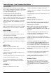
1- Bolt
2 - Front Cover
3 - Oil Cooler
4 - Adaptor
5 - Anti-Vibration Mounting
Fig. 1 - Exploded View Of Disc Brake Oil Cooler
DESCRIPTION AND OPERATION
Numbers in parentheses refer to Fig. 1. The disc brake
oil cooler can be identified as item 6 in Section 210-
0005, COOLING SYSTEM SCHEMATIC.
The disc brake oil cooler is a blast air type, mounted
on the right hand fender adjacent to the main hydraulic
tank. The fan (7) within the brake oil cooler is driven by
a hydraulic motor (10). The motor (10) is supplied by a
dedicated brake cooling section of the triple gear pump,
via two speed control valve. The speed of the fan (7) is
dependant on the oil flow being supplied to the motor
(10) from the two speed control valve. Refer to Section
250-0065, TWO SPEED CONTROL VALVE.
Brake cooling oil enters the top of the oil cooler (3) and
flows through the oil cooler (3) before exiting at the
bottom. There are three inlet ports and three outlet
ports, one for each axle.
REMOVAL
Numbers in parentheses refer to Fig. 1.
WARNING
To prevent personal injury and property
damage, make sure blocking or lifting
equipment is properly secured and of adequate
capacity to do the job safely.
1. Position the machine on a level floor, apply the
parking brake and switch off the engine. Operate the
steering several times to discharge the steering
system. Operate the treadle valve continuously to
discharge the braking system.
2. Block all road wheels and place the battery master
switch in the off position. Place steering lock bar in the
locked position.
11 - Bolt
12 - Washer
13 - Isolation Mount
14 - Locknut
15 - Bolt
6- Casing
7- Fan
8 - Fan Plate Assembly
9 - Rear Guard Assembly
10 - Hydraulic Motor
COOLING SYSTEM - Disc Brake Oil Cooler