
Operation and maintenance manual


Section 210-0046
1
SM 2164 Rev 1 10-03
2
1
DESCRIPTION
Numbers in parentheses refer to Fig. 1. The low
pressure relief valve can be identified as item 8 in
Section 210-0005, COOLING SYSTEM SCHEMATIC.
Mounted to the engine side of the brake coolant tank, the
low pressure relief valve houses three separate relief
valve cartridges (1).
The low pressure relief valve is installed between the
motor/triple pump and the six brake packs (two per
axle). Each relief valve (1) limits the maximum
pressure of brake cooling oil supplied to each brake
pack. One relief valve per axle. Refer to Section 250-
0045, MOTOR/TRIPLE PUMP ASSEMBLY.
OPERATION
Numbers in parentheses refer to Fig. 1.
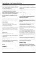
Refer to Fig. 2. Brake cooling oil is supplied to each
inlet port of low pressure relief valve from a dedicated
section of the motor/triple pump, and is then fed to a
manifold block on each axle, which distributes oil to
each brake pack. The common return line for the relief
cartridges (1) feeds directly back to the brake coolant
tank.
All three relief valve cartridges (1) are preset to 1.5 bar
(22 lbf/in²). This setting limits the brake cooling oil
pressure across each brake pack to 1.0 bar (14.5 lbf/
in²) maximum. Brake pack oil pressure greater than
1.0 bar (14.5 lbf/in²) will be detrimental to the brake
pack seals.
FAULT DIAGNOSIS
Numbers in parentheses refer to Fig. 1. The valve
could possibly fail one of two ways. Either the relief
cartridge (1) remains open or closed.
If the relief cartridge (1) remains open, all of the brake
cooling oil will be diverted straight back to the brake
coolant tank, bypassing the disc brake oil cooler. This
will result in dangerously high oil temperatures. If the
relief cartridge (1) remains closed, oil pressure will be
allowed to build up across the brake packs, eventually
causing seals to be damaged.
If the relief cartridge (1) remains open or leaks
excessively, the fault is likely to be due to debris on
the relief cartridge (1) seat. In this case remove the
relief cartridge (1) and clean. However, it is very likely
that the seat will be damaged, so it is advised that a
new cartridge (1) should be installed.
REMOVAL
Numbers in parentheses refer to Fig. 1.
WARNING
To prevent personal injury and property
damage, ensure wheel blocks, blocking
materials and lifting equipment are properly
secured and of adequate capacity to execute
the job safely.
1. Position the vehicle in a level work area, apply the
parking brake and switch off the engine. Operate
treadle valve continuously to relieve pressure in the
braking system.
2. Block all road wheels and place the battery master
switch in the 'Off' position. Place the steering lock bar
in the 'Locked' position.
3. Remove blanking cap from remote drain line at the
COOLING SYSTEM - Low Pressure Relief Valve
SM - 2778
Fig. 1 - Low Pressure Relief Valve
1 - Low Pressure Relief Cartridge
2 - Plug
SM - 2758
Fig. 2 - Low Pressure Relief Valve Schematic
TO AXLES
REAR
CENTRE
FRONT
FROM MOTOR/
TRIPLE PUMP
TO BRAKE
COOLANT TANK