
Operation and maintenance manual


Section 210-0045
1
SM 2152 6-02
DESCRIPTION
The low temperature unloader valve can be identified
as item 3 in Section 210-0005, COOLING SYSTEM
SCHEMATIC. Numbers in parentheses refer to Fig. 1.
Located on the hydraulic cradle, below the hydraulic
diverter tube, the low temperature unloader valve houses
the following:
(1) two way solenoid operated cartridge valve with open
and closed positions
(2) relief valve cartridge assembly
(3) check valve cartridge assembly.
The low temperature unloader valve receives hydraulic
supply from the engine cooling section (mid section) of
the triple gear pump. An integral two way solenoid
cartridge (1) controls flow to the hydraulically driven
engine cooling fan. The pressure relief valve (2)
controls circuit pressure to a preset 205 bar (2970 lbf/
in²).
OPERATION
Numbers in parentheses refer to Fig. 1.
The low temperature unloader valve forms part of the
engine cooling fan circuit. The integral solenoid valve
(1) controls the two speed engine cooling fan motor
and the relief valve (2) maintains a safe working circuit
pressure of 205 bar (2970 lbf/in²).
The low temperature unloader valve has two ports, an
inlet port (P) and an outlet port (T). The inlet port (P) is
protected by the relief valve (2) which, although
adjustable, should be preset to 205 bar (2970 lbf/in²).
The relief valve has a separate internal pilot
connection which, when vented to the outlet port (T),
allows the relief valve to pass flow at a very low
pressure from the inlet port (P) to the outlet port (T).
Refer to Fig. 2. The solenoid valve (1) provides a
means to opening this pilot connection to the outlet
port (T). This connection is made when the solenoid
valve is energised. The solenoid valve is energised on
ignition contact, when a 24V signal is supplied to the
solenoid valve from the engine ECU. With the solenoid
valve energised no pressure can be raised at the inlet
port (P). A minimum flow will circulate the engine
cooling fan motor allowing it to rotate. This minimum
flow is supplemented by the relief flow via the priority
unloader valve. Refer to Section 250-0075, PRIORITY
UNLOADER VALVE.
Refer to Fig. 3. The solenoid valve (1) is de-energised
when the voltage from the engine ECU drops to 0V.
The voltage signal is cut to 0 volts when the engine
E.C.U. senses any one of the following 4 pre-
programmed parameters:
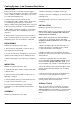
SM - 2742
Fig. 1 - Low Temperature Unloader Valve
SM - 2744
Fig. 2 - Low Temperature Unloader Valve -
Solenoid Energised
SM - 2743
Fig. 3 - Low Temperature Unloader Valve -
Solenoid De-energised
1 - Solenoid Valve
2 - Relief Valve
3 - Check Valve
FROM
TRIPLE
GEAR
PUMP
TO
TANK
FROM
TRIPLE
GEAR
PUMP
TO
TANK
COOLING SYSTEM - Low Temperature Unloader Valve
2
1
3
T
P
T
P