
Operation and maintenance manual


Section 210-0000
Cooling System - Cooling System (Series 60 Engine)
SM 2117 Rev 1 11-03
2
OPERATION
Numbers in parentheses refer to Fig. 1, unless
otherwise specified.
Upon starting a cold engine or when the coolant is
below operating temperature, the coolant is restricted
at thermostat housing (7) and bypass line (12) provides
water circulation within the engine during the warm-up
period.
Note: Engine coolant thermostats start to open at
88° C (190° F) and are fully open at 96° C (205° F).
Engine water pump (3) draws coolant from the radiator
through radiator outlet pipe (9). Engine water pump (3)
then pumps coolant through coolant pipe (10) into
transmission oil cooler (5). Coolant flows through
transmission oil cooler (5), drawing heat from the
transmission oil cooler, and then flows through coolant
pipe (11) and into engine oil cooler (6). The coolant
then flows through the engine block and passes up
through the cylinder head to thermostat housing (7).
Aerated coolant is drawn off to header tank (1) from
thermostat housing (7) through deaeration line (14).
Excess coolant at header tank (1) is discharged
through an overflow line from the filler neck.
When the coolant reaches operating temperature, the
thermostats open allowing coolant to flow into the
radiator through radiator inlet pipe (13). The coolant
passes through a series of tubes in radiator assembly
(2) core, where the coolant temperature is lowered by
the air stream created by the revolving fan, and into the
radiator outlet pipe (9) to be re-circulated back through
the system.
Aerated coolant is drawn off to header tank (1) from the
radiator, radiator inlet pipe (13) and thermostat housing
(7) through deaeration lines (14). Excess coolant at
header tank (1) is discharged through an overflow line
from the filler neck.
The use of antifreeze is mandatory with the cooling
system. The lack of coolant flow through the radiator
with the thermostats closed allows the coolant in
radiator assembly (2) to freeze under low ambient
temperature conditions.
Coolant Filter
The cooling system is protected by a replaceable spin-
on type coolant filter (4) and conditioner mounted on
the gear case cover at the front right hand side of the
engine. The filter provides mechanical filtration by
SM - 1221
means of a closely packed element through which the
coolant passes. Any impurities such as sand and rust
particles suspended in the cooling system will be
removed by the straining action of the element. The
removal of these impurities will contribute to longer
engine water pump (3) life and proper operation of the
thermostats.
Coolant filter (4) also serves to condition the coolant by
softening the water to minimize scale deposits,
maintain an acid-free condition and act as a rust
preventive. Corrosion inhibitors are placed in the
element and dissolve into the coolant, forming a
protective rustproof film on all of the metal surfaces of
the cooling system.
Coolant flows from engine water pump (3) through filter
inlet line (15) and into coolant filter (4). Coolant flows
through the filter element and exits through filter outlet line
(16) and into the engine block. Shut-off cocks on both filter
lines allow coolant filter (4) to be replaced with the
minimum loss of coolant.
Air-To-Air Charge Cooling
Numbers in parentheses refer to Fig. 2.
In the air system used on the Series 60 engines,
outside air drawn into the engine through the air
cleaner, passes through the air filter element and is
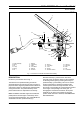
Fig. 2 - Air-to-Air Charge Cooler Lines and Flow
1 - Radiator Assembly
2 - Air-to-Air Charge Cooler
3 - Inlet Pipe
4 - Outlet Pipe
5 - Outlet Pipe
6 - Inlet Pipe