
Operation and maintenance manual


Section 210-0000
SM 2117 Rev 1 11-03
1
COOLING SYSTEM - Cooling System (Series 60 Engine)
SM - 2664
DESCRIPTION
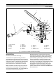
Numbers in parentheses refer to Fig. 1.
A radiator and fan cooling system is used on Series 60
engines installed in these vehicles. This system has a
centrifugal type water pump (3) to circulate coolant
throughout the system. Two full blocking type
thermostats located in thermostat housing (7), attached
to the right hand side of the cylinder head, control the
flow of coolant.
Fig. 1 - Cooling Lines and Flow
1 - Header Tank
2 - Radiator Assembly
3 - Engine Water Pump
4 - Coolant Filter
5 - Transmission Oil Cooler
6 - Engine Oil Cooler
7 - Thermostat Housing
8 - Make-up Line
9 - Radiator Outlet Pipe
10 - Coolant Pipe
11 - Coolant Pipe
12 - Bypass Line
13 - Radiator Inlet Pipe
14 - Deaeration Lines
15 - Filter Inlet Line
16 - Filter Outlet Line
The main components of the cooling system are;
header tank (1), radiator assembly (2), engine water
pump (3), coolant filter (4), transmission oil cooler (5),
engine oil cooler (6) and thermostat housing (7).
Attached to the front of radiator assembly (2) are an
air-to-air charge cooler, a fuel cooler and a hydraulic oil
cooler.
1
14
7
12
13
2
8
9
15
4
16
3
11
5
10
6