
Operation and maintenance manual


Section 200-0051
Fuel System - Electronic Foot Pedal
SM 1399 5-98
2
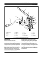
REMOVAL
Numbers in parentheses refer to Fig. 1.
WARNING
To prevent personal injury and property
damage, be sure wheel blocks are properly
secured and of adequate capacity to do the job
safely.
1. Position the vehicle in a level work area, ensure the
body is fully lowered, apply the parking brake and
switch off the engine. Turn steering wheel in both
directions several times to relieve any pressure in the
steering circuit.
2. Block all road wheels and place the battery master
switch in the 'Off' position.
3. Disconnect electrical harness (18) and kickdown
switch (17) harness.
4. Move cab floor mat back and clear from pedal
assembly (1) and mounting plates.
5. Remove mounting hardware securing plate (9) and
pedal assembly (1) to cab floor plate. Remove plate (9)
and pedal assembly (1).
6. Remove bolts (20), nuts (21) and lockwashers (22)
securing pedal assembly (1) to plate (9). Remove
pedal assembly (1) from plate (9).
INSTALLATION
Numbers in parentheses refer to Fig. 1.
Note: Tighten all fasteners to standard torques listed
in Section 300-0080, STANDARD BOLT AND NUT
TORQUE SPECIFICATIONS.
1. Position pedal assembly (1) on plate (9) and secure
with bolts (20), lockwashers (22) and nuts (21).
2. Secure plate (9) and pedal assembly (1) to the cab
floor plate with mounting hardware removed during
removal.
3. Connect electrical harness (18) and kickdown
switch (17) harness.
4. Position floor mat on cab floor and ensure that pedal
assembly (1) is free to operate.
5. Place the battery master switch in the 'On' position,
remove wheel blocks and start the engine. Ensure that
pedal assembly (1) operates correctly.
Note: The engine MUST be started with the foot 'OFF'
pedal assembly (1).
MAINTENANCE
Limited repair of the electronic foot pedal assembly is
by replacement of parts only. Refer to vehicle Parts
Book for part numbers of overhaul kits.
* * * *